background image

432-0010-00-10 Rev 100 — MD-Series Operator’s Manual 

29

 IP Communications

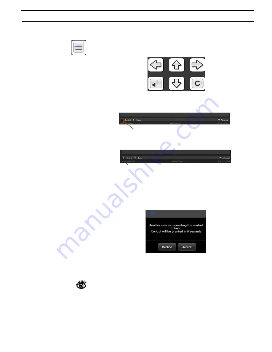
When the On-Screen Menu button is selected, the Toolbar changes to the 

following buttons to allow the user to navigate the menus. In the order they 

appear, the buttons are Left, Up, Right, Enter, Down, and Cancel.

Initially, the camera will not respond to any commands until the user takes control 

of the camera. A “Control” light in the lower left indicates if the user has control of 

the camera or not.

Clicking on the Control light or one of the buttons will send a control request to the 

camera. 

Multiple Control Devices

It is possible to have multiple devices that can control the camera on the network. 

If one device has control and a second device sends a control request to the 

camera, the first device receives the following message. 

If the control request is not declined within the allotted time, the other device will 

take control of the camera. The control light in the bottom left corner will change to 

yellow, indicating the device is connected, but not controlling the camera. 

Note:

Additional information about the web interface is available in the section 

titled “Advanced IP Communications” on page 31.

Control not lit, indicating no control yet

Control light indicates the PC has control of the camera

Summary of Contents for MD-Series

Page 1: ...MD Series 432 0010 00 10 Revision 100 March 2013 Operator s Manual ...

Page 2: ...ime Document Number 432 0010 00 10 Revision 100 Document History Proper Disposal of Electrical and Electronic Equipment EEE The European Union EU has enacted Waste Electrical and Electronic Equipment Directive 2002 96 EC WEEE which aims to prevent EEE waste from arising to encourage reuse recycling and recovery of EEE waste and to promote environmental responsibility In accordance with these regul...

Page 3: ... System Startup 13 System Startup and Shutdown 13 The Bootup Process 13 CHAPTER 3 MD Series System Configuration 15 Overview 15 Main Menu 16 Video Setup Menu 17 Set Thermal Color Default 17 Set Video Polarity 17 Enable Disable Color Thermal Video 18 Display Test Pattern 18 Set Symbology Menu 19 Disable Enable PC Icon and JCU Icon 19 Display All Icons 19 Display Minimal Icons 19 Hide All Icons 20 U...

Page 4: ... Setup and Maintenance Menus 32 Changing the IP Address 32 Changing the Login Passwords 34 Custom Network Applications 35 Programmers Integrators 35 Resources Available 36 Training 36 Enabling Universal Plug and Play UPnP 36 CHAPTER 5 Optional Joystick Control Unit JCU 39 JCU Introduction 39 JCU Buttons 40 Power DIM Button 40 MENU Button 40 USER Button 41 SCENE Button 41 COLOR Button 42 HOME Butto...

Page 5: ...y 47 Calibrate JCU 47 Cancel 48 Changing the IP Address of the JCU 48 CHAPTER 6 MD Series Reference Information 51 Introduction 51 Acronyms 51 List of Icons 53 System Specifications 54 Feature Comparison of MD Series Models 55 Troubleshooting Tips 56 On Screen Messages 58 Restoring the Factory Network Settings 59 ...

Page 6: ...4 432 0010 00 10 Rev 100 MD Series Operator s Manual This page is intentionally blank ...

Page 7: ...ts refer to the phone numbers listed on the back cover of this manual This manual includes information about the following topics System description System startup and shutdown Configuring the MD Series camera Using a smartphone iOS device or web browser to control the camera Using an optional JCU to control the camera Reference information including acronyms parts lists a table of icons and syste...

Page 8: ... this manual when handling and operating the MD Series camera system Warning Warning notices are used to emphasize that hazardous voltages currents temperatures or other conditions that could cause personal injury or death exist with this equipment or may be associated with its use Caution Caution notices are used where equipment might be damaged if care is not taken or an operation might have an ...

Page 9: ... equipment such as Power over Ethernet PoE switches and routers can be used to interconnect these components MD Series Dome Assembly The MD Series thermal camera is contained in the ball of the dome assembly which has a removable cover that protects the camera assembly inside The outer dome is not intended to provide camera sealing When the cover is removed at the time of installation the camera a...

Page 10: ...emotely while the camera is operating Control of the camera is limited to making adjustments to the image and to accessing an on screen configuration menu The possible control functions or image adjustments are described in Chapter 3 MD Series System Configuration on page 15 Depending on how much control is needed and what devices are available there are several options for controlling the camera ...

Page 11: ...thermal infrared band to produce images by sensing subtle differences in temperature and generating images based on those differences Fortunately this type of thermal energy comes from everything around us even cold objects like ice Unlike ordinary cameras and unlike the human eye the MD Series does not produce images from visible light energy which only comes from things that are very hot such as...

Page 12: ...ymbol display The following image of a screen illustrates some of the possible icons displayed by the system as well as an example of the on screen menu that can be used to change system settings The on screen menus are described in Chapter 3 MD Series System Configuration on page 15 A complete list of all of the icons used in the system and a brief description of each icon s meaning can be found ...

Page 13: ...tment Which setting to use depends on personal preference and environmental conditions the Man Overboard setting my look optimal even when running on open water during the daytime Rearview Icon The rearview icon indicates the rearview mode option has been selected in the System Settings menu The rearview setting flips the video image horizontally left to right The image on the display provides the...

Page 14: ...n in the on screen menu the network settings including DHCP or static mode IP address and so on are not restored to factory defaults Refer to Chapter 3 MD Series System Configuration on page 15 for information about the on screen menus Refer to Chapter 4 IP Communications on page 25 for information about setting the IP network parameters TABLE 1 1 Factory Default Settings Option Factory Default Se...

Page 15: ...h a short boot up sequence and then it will be fully functional The Bootup Process When starting from a full shutdown make sure the monitor is turned on then power on the system When power from the circuit breaker is initially applied to the system the camera will begin a bootup sequence Once the bootup has completed approximately 60 seconds later the camera will be operating and generate a video ...

Page 16: ...lly boots up in white hot mode by default unless the default color has been changed using the system settings see page 17 After the bootup sequence the camera is ready to use Note Unlike the FLIR M Series cameras the MD Series camera does not have a standby mode If the camera is not being used and it is desirable to save energy it is necessary to turn off the power to the camera Red Hot Mode White...

Page 17: ...rtphone or PDA Apple iOS device such as an iPad or iPhone using the free FLIR Mobile application available through the Apple iTunes store Multi Function Display MFD from Raymarine or other vendor FLIR Joystick Control Unit JCU The way the camera is controlled varies depending on which device is used If a laptop is used with the web interface a mouse or trackpad is used to select a button or link o...

Page 18: ...enu selection is indicated by the red bar If a default choice is available it displays in boldface type If a menu entry begins with the word Enable for example Enable Color Thermal Video then that option is currently disabled When it is selected the option becomes enabled and the word Enable changes to Disable Similarly if an option begins with Disable selecting that menu entry will disable the op...

Page 19: ...m is rebooted Black Hot polarity darker colors represent hotter objects the factory default White Hot polarity lighter colors represent hotter objects The difference between white hot and black hot is shown below using a grayscale color palette white hot is on the left and black hot on the right The use of white hot or black hot display mode is strictly a personal preference experiment with the di...

Page 20: ...CU COLOR button This is the factory default setting Enable Color Thermal Video Five palettes display as you repeatedly press the JCU COLOR button grayscale red glowbow rainbow and fusion With the Set Thermal Color Default option it is possible to set a default for the system to use the next time it is started This setting is used in combination with the Video Polarity setting Inverting the color p...

Page 21: ... device such as a smartphone or iPad on the network This happens only when you have completed the setup described in Chapter 4 IP Communications on page 25 Display All Icons Selecting this option maximizes the display of the on screen icons Some icons such as home are only displayed momentarily If you choose to display all icons it is possible to turn off the display of the JCU and PC icons by dis...

Page 22: ... Man Over Board settings A shor t press of the USER button causes the thermal camera to use the Man Overboard AGC setting This is one of the settings available from the SCENE button see page 41 Hide Show All Icons A short press of the USER button switches between the Hide All Icons setting an d Display All Icons refer to Set Sym bology Menu on page 19 for more information Invert Video Polarity A s...

Page 23: ...le Disable Rearview Mode This menu entry enables or disables the rearview mode which causes the video image to be flipped horizontally revert The image on the display provides the same perspective as a rear view mirror in a vehicle objects off the stern on the starboard side of the vessel are displayed on the right hand side of the video When rearview mode is enabled the rearview mirror icon is di...

Page 24: ... When you are finished select Exit About Help Menu When you select About Help from the main menu the following on screen menu displays Video Icon Help Screens The Video Icon Help Screens provide an on screen explanation of the meaning of each of the screen icons The icons are shown on two screens MD 625 JD 0123 Edit Camera Name and press puck when finished Confirm new Camera Name Cancel Exit Press...

Page 25: ...for the MD Series camera you are using such as the camera model serial number and software release information If there are any problems with the camera it is useful to have this information available when contacting FLIR technical support An example of the display is shown below Name MD 625 S N JD0123 MAC 00 40 7f 40 60 40 v2 5 10 6 Built 12 Jan 2013 MCU ver Exit ...

Page 26: ...ual When contacting FLIR please have the product information available Restore Factory Defaults Select Restore Factory Defaults to restore the MD Series to its factory default settings The camera will prompt you to confirm before continuing Refer to Table 1 1 on page 12 for a list of the factory default settings FLIR CVS Maritime 70 Castilian Drive Goleta CA 93117 1 877 773 3547 www FLIR com cvs m...

Page 27: ...e iOS device such as an iPad or iPhone The app is similar to the web browser interface and supports basic camera functions More advanced IP features and configuration settings including IP address changes are described in the Advanced IP Communications on page 31 For information about FSM refer to the FSM User Manual Getting the camera IP interface set up and working may require a level of familia...

Page 28: ...est and learn about the presence and capabilities of other devices For computers running Windows 7 or 8 the system automatically detects network devices and displays them under the Network locations In older versions of Windows the UPnP capabilities must be enabled to allow devices to be detected in My Network Places When a PC is configured to accept UPnP broadcasts UPnP devices on the network wil...

Page 29: ... versions Most people will use the user login to send commands to the camera with the Toolbar User Name user Password fliradmin In some cases it may be necessary to use one of the following logins in order to access more advanced camera settings For a brief description of some of the advanced settings refer to Setup and Maintenance Menus on page 32 For additional configuration information refer to...

Page 30: ...con cycles through the five color settings available when Color Thermal Video is enabled grayscale red glowbow rainbow and fusion This action is the same as pressing the JCU COLOR button Change Scene Settings Clicking the icon cycles through four preset automatic gain control AGC settings Night Running Night Docking Day Running Man Overboard This is the same as a short press of the SCENE button on...

Page 31: ...ol request to the camera Multiple Control Devices It is possible to have multiple devices that can control the camera on the network If one device has control and a second device sends a control request to the camera the first device receives the following message If the control request is not declined within the allotted time the other device will take control of the camera The control light in t...

Page 32: ...e network Then the mobile device must be set up to join the Wi Fi network Settings Wi Fi To obtain the FLIR Mobile App open the App Store application and search for FLIR Locate the FLIR Mobile App and select INSTALL Once the app is installed select OPEN to start it When the application is started it searches the network for any cameras The app will connect to the first camera it finds If more than...

Page 33: ...mmand strings and responses that are sent back and forth with the camera For programmers and integrators a command string can be typed in manually and transmitted to the camera by clicking the TX button This can be useful when testing a new application The commands sent back and forth are part of a communication protocol known as the FLIR Network Application Programming Interface API For custom ne...

Page 34: ...ork settings including the IP address of the camera It is also possible to use the Maintenance menu to change the login passwords and to allow users logging in as user or expert to set their own passwords The Maintenance menu also provides access to many other configuration options which are not described in this manual For additional configuration information refer to the Nexus IP Camera Configur...

Page 35: ... IP address is changed the browser window which was opened under the old IP address is no longer valid The new camera address is likely from a completely different network than the old address It may be necessary to change the IP address on the PC now as well Once the PC and camera are on the new network type the new static IP address into the browser address field or return to Network Win 7 8 or ...

Page 36: ...cess either by IP address or by login passwords The login passwords for each of the three logins can be changed by the system administrator to prevent unauthorized logins The administrator can allow users logging in as user or expert to set their own passwords by selecting the option Allow change password When this is selected along the top of the screen th ere will be a small Change Password icon...

Page 37: ...and other marine electronics such as radar in advanced networks The SDK accelerates any application programming with FLIR Systems thermal imaging cameras and lets integrators combine camera functionality with other sensors and detection devices to take full advantage of this advanced technology Nexus implements a text based common gateway interface CGI using a simple grammar to format commands goi...

Page 38: ...rested in learning about thermal imaging cameras FLIR offers complimentary training courses at the Infrared Training Center http www flir com training Enabling Universal Plug and Play UPnP In order to use the Web interface it may be necessary to enable Universal Plug and Play UPnP on the PC When UPnP is not enabled the camera and JCU will not appear under My Network Places UPnP is not enabled by d...

Page 39: ...sible to determine if any UPnP enabled devices exist on the network by opening My Network Places If there are UPnP devices on the local network they will appear here with a generic icon based on the device type In the future when a UPnP device is installed on the network a notifying icon will appear briefly in the System Tray When this icon is displayed go to My Network Places to view the new devi...

Page 40: ...IP Communications 38 432 0010 00 10 Rev 100 MD Series Operator s Manual This page is intentionally blank ...

Page 41: ...ular button it is possible to refer to that chapter for additional details FLIR Joystick Control Unit JCU A JCU can optionally be installed and used to control the camera The JCU can be used to change the image settings or to zoom the camera and to configure the camera by means of on screen menus The JCU connects to the camera using an Ethernet network connection The JCU receives power through a P...

Page 42: ...M button cycles through the four levels of brightness for the JCU display The JCU controls are backlit to make them easier to see at night Use this button to adjust the brightness of the JCU backlighting Long Press Pressing and holding the Power DIM button is used to access the JCU Power menu and accessing system functions such as calibrating the JCU and associating the JCU with a camera These fun...

Page 43: ... User Programmable Button menu entry see page 20 Short Press A short press of the USER button is initially configured to invert the video polarity setting from white hot to black hot It is possible to choose from a number of other options Long Press Pressing and holding the USER button displays the on screen menu for programming the button The menu can also be accessed by pressing the MENU button ...

Page 44: ... is often used at night in the darkness some users may prefer the red hot image to help preserve the user s night vision Based on personal preferences one of the other color settings or color palettes may be chosen as a default Note The USER button is configured to invert the video polarity setting by default so it changes the infrared imagery from white hot red hot to black hot Long Press Press a...

Page 45: ...eaker While this option can be selected from the JCU Power Menu pressing and holding the SCENE COLOR and HOME buttons at the same time will also put the system in standby mode Display JCU IP Address If you press the COLOR button while pushing the puck the IP address of the JCU displays on the JCU screen Button Summary Table 5 1 summarizes the action of each button on the JCU TABLE 5 1 Summary of B...

Page 46: ...k to select a menu item Zooming the Camera By default push the puck in and hold it 1 second to turn on 2X electronic zoom on the IR camera Push and hold for 2 seconds for 4X zoom M 625 model Pull up on the puck to return to 2X zoom and pull again to return to no zoom The screen icon changes to indicate the settings It is possible to change this so that you zoom in by twisting the puck clockwise zo...

Page 47: ... power The JCU LCD screen displays Starting then Searching When the last used camera is found the message changes to Connecting which continues to flash until the connection process completes Important Fully establishing a connection may take up to a minute Please be patient while the system verifies each component If this is the very first time the JCU has been used to connect to the camera it is...

Page 48: ... menu choices by moving the puck down or by rotating the puck clockwise An up arrow indicates the last menu entry is displayed and the other choices must be accessed by moving the puck up or by rotating the puck counterclockwise A double arrow indicates it is possible to move up or down in the menu The Power Menu displays the following menu options Power Menu Assign JCU JCU Stndby Camera Stndby Sy...

Page 49: ...pport this option This function is used to properly shut down all cameras return to stow position and JCUs prior to removing power with the system breaker Note Global Stndby displays as an option only when multiple JCUs or cameras are found on the system Global standby can also be achieved by pressing and holding the SCENE COLOR and HOME buttons in unison Calibrate JCU Calibrate JCU is used to sta...

Page 50: ...ddress is displayed by pressing the COLOR button and puck at the same time The IP is displayed for 3 seconds and then the display returns to the camera name or other the state it was in before the IP request was made On networks with specific requirements you may need to assign the JCU a static IP address You do this using steps similar to the way you changed the camera IP address 1 Determine the ...

Page 51: ...twork Mask should fill in automatically for example 255 255 255 0 5 Click Save to save the changes and exit the control page When software updates become available it is possible to use the Firmware Update field to load the update to the camera Contact the FLIR dealer where you purchased the camera for additional information or contact FLIR directly ...

Page 52: ...Optional Joystick Control Unit JCU 50 432 0010 00 10 Rev 100 MD Series Operator s Manual This page is intentionally blank ...

Page 53: ...odel It also includes a set of tips for troubleshooting issues Acronyms Table 6 1 lists each acronym that is used in this manual and its meaning TABLE 6 1 Acronyms Acronym Term Definition AGC Automatic Gain Control ANSI American National Standards Institute API Application Programming Interface EAR Export Administration Regulations EMI Electromagnetic Interference FFC Flat Field Correction FLIR Fo...

Page 54: ...et Protocol IR Infrared or thermal JCU Joystick Control Unit LCD Liquid Crystal Display MFD Multifunction display NMEA National Marine Electronics Association NTSC National Television System Committee PAL Phase Alternating Line PoE Power over Ethernet SCTE Society of Cable Telecommunications Engineers SDK Software Developer s Kit UPnP Universal Plug and Play VDC Volts Direct Current TABLE 6 1 Acro...

Page 55: ... Multiple JCUs Indicates more than one JCU is connected to the camera PC Indicates a PC or other wireless device such as a smartphone or an iPad on the network has a connection with the camera It is possible to use the PC or device to control the camera Rearview Mode Indicates camera is in rearview mode so that images are flipped horizontally Scene Night Running One of four p automatic gain contro...

Page 56: ... Joystick Weight 45 kg 1 lb Power Camera Input Power Power over Ethernet PoE per IEEE 802 3af JCU Input Power Power over Ethernet PoE per IEEE 802 3af Consumption camera and FLIR PoE injector 7 5W Nominal without heater 18 W Nominal with heater Environmental Operating temperature range 25 C to 55 C 11 F to 131 F Storage temperature range 30º C to 70º C 22º F to 158º F Automatic Window defrost Stan...

Page 57: ...mbers Video Format Thermal Video Resolution Thermal Frame Refresh Rate HFoV Digital Zoom MD 324 432 0010 01 00S NTSC 320 x 240 9 Hz 24 2x 432 0010 01 00 NTSC 320 x 240 30 Hz 24 2x 432 0010 02 00S PAL 320 x 256 9 Hz 24 2x 432 0010 02 00 PAL 320 x 256 25 Hz 24 2x MD 625 432 0010 03 00S NTSC 640 x 480 9 Hz 25 2x and 4x 432 0010 03 00 NTSC 640 x 480 30 Hz 25 2x and 4x 432 0010 04 00S PAL 640 x 512 9 H...

Page 58: ... anti reflective coating degrade the camera s performance and void the camera warranty The camera housing has a durable marine coating Rinse the camera housing with very low pressure fresh water to keep it clean If the front window of the camera gets water spots wipe it with a clean lens cloth folded in fourths and dampened with fresh water Noisy image A noisy image is usually attributed to a cabl...

Page 59: ...ts in the scene are wet rather than dry such as on a foggy day or in the early morning when everything may be coated with dew Under these conditions it may be difficult for the camera to show the temperature the object itself rather than of the water coating Eastern or Western exposure While a boat is under way the camera may inevitably end up pointing directly east or west and this may cause the ...

Page 60: ...r is true only of JCUs If you are using the Web interface to control the camera with a browser on a PC or smartphone a message displays prompting you to release control before the other Web device assumes it On Screen Messages In some circumstances a status or alert message may appear on the video screen This section describes the messages and the appropriate actions that may be necessary Loading ...

Page 61: ... of the received packet indicates the camera has a custom loopback connector installed on its Ethernet interface The detection of the loopback packet cues the camera to restore factory defaults and to revert to the same configuration and behavior as when the camera left the factory The following table describes the loopback connector The RJ45 loopback termination ties pin 1 to pin 3 and pin 2 to p...

Page 62: ...MD Series Reference Information 60 432 0010 00 10 Rev 100 MD Series Operator s Manual ...

Page 63: ...NOTES ...

Page 64: ... FX 1 805 685 2711 sales flir com EUROPE CS Eurasian Headquarters FLIR Systems CVS BV Charles Petitweg 21 4847 NW Teteringen Breda Netherlands PH 31 0 765 79 41 94 FX 31 0 765 79 41 99 flir flir com FLIR Systems Inc Corporate Headquarters FLIR Systems Inc 27700A SW Parkway Ave Wilsonville OR 97070 USA PH 1 503 498 3547 PH 1 877 773 3547 FX 1 503 498 3153 sales flir com ...

Reviews: