background image

FLIR


IM75


USER


GUIDE


Document


Identifier:


IM75

en

US_AA


17

5.10


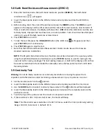
Diode


Test


Warning:


Do


not


do


diode,


resistance


or


continuity


tests


before


you


have


removed


the


power


from


capacitors


and


other


devices


under


test


during


a


measurement.


Injury


to


persons


can


occur.


1.


Set


the


function


switch


to


the


position.


2.


Insert


the


black


probe


lead


into


the


COM


terminal


and


red


probe


lead


into


the


V


terminal.


3.


Use


the


MODE


button


to


select


the


diode


test


function.


The


indicator


will


be


displayed.


4.


Insert


the


black


probe


lead


into


the


COM


(negative)


terminal


and


the


red


probe


lead


into


the


positive


terminal.


5.


Touch


the


tips


of


the


probe


across


the


diode


or


semiconductor


junction


under


test.


Make


a


note


of


the


value


on


the


display.


6.


Reverse


the


polarity


of


the


probes,


by


interchanging


the


probe


test


locations.


7.


Touch


the


tips


of


the


probe


across


the


diode


or


semiconductor


junction


under


test.


Make


a


note


of


the


new


value


on


the


display


5.11


Capacitance


Measurements


Warning:


Do


not


do


capacitance


tests


before


removing


the


power


to


the


capacitor


or


other


devices


under


test


during


a


measurement.


Injury


to


persons


can


occur.


1.


Set


the


function


switch


to


the

position.


2.


Use


the


MODE


button


to


select


the


capacitance


measurement.


The


F


(Farad)


unit


will


be


displayed.


3.


Insert


the


black


probe


lead


into


the


COM


(negative)


terminal


and


the


red


probe


lead


into


the


positive


terminal.


4.


Touch


the


tips


of


the


probe


across


the


part


under


test.


5.


Read


the


capacitance


value


on


the


display.


Note:


For


very


large


capacitance


values,


it


may


take


several


seconds


for


the


measurement


to


settle


and


the


final


reading


to


stabilize.


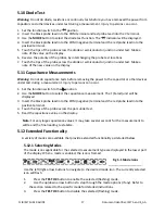
5.12


Extended


Functionality


A


variety


of


modes


are


available


that


provide


extended


functionality


as


detailed


below.


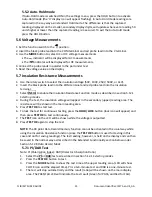
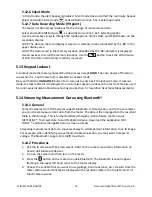
5.12.1


Selecting


Modes


The


mode


icons


applicable


for


the


selected


measurement


type


are


displayed


in


the


lower


part


of


the


display.


When


a


mode


is


enabled,


the


icon


is


framed.


Use


the


left/right


arrow


buttons


to


navigate


to


the


desired


mode


icon.


The


currently


selected


icon


will


flash.


1.


Press


the


TEST


OK


button


to


enable


the


selected


(flashing)


mode.


2.


Use


the


up/down


arrow


buttons


to


step


through


the


mode


options


(if


any).


Refer


to


the


section


related


to


the


specific


mode


for


detailed


instructions.


3.


Press


the


TEST


OK


button


to


disable


the


selected


(flashing)


mode.


Fig


5

1


Mode


Icons


Summary of Contents for IM75

Page 1: ...USER MANUAL FLIR MODEL IM75 Insulation Tester MultiMeter ...

Page 2: ...h Positions 10 4 3 Function Buttons Selector Pad and Rotary Switch 10 4 3 1 Selector Pad 11 4 3 2 Rotary Switch 11 4 4 Display Description 12 4 5 Display Icons and Indicators 13 5 OPERATION 14 5 1 Powering the Meter 14 5 1 1 Auto Power Off 14 5 2 Manual AC DC Selection 14 5 3 Auto Range 14 5 4 Smart Out of Range Warnings 14 5 5 Data Hold and Auto Hold Modes 14 5 5 1 Data Hold Mode 14 5 6 Voltage M...

Page 3: ...rding Mode 99 point 19 5 13 Keypad Lockout 19 5 14 Streaming Measurement Data using Bluetooth 19 5 14 1 General 19 5 14 2 Procedures 19 6 MAINTENANCE 20 6 1 Cleaning and Storage 20 6 2 Battery Replacement 20 6 3 Fuse Replacement 20 6 4 Disposal of Electronic Waste 20 7 SPECIFICATIONS 21 7 1 General specifications 21 7 2 Electrical Range Specifications 22 7 3 Input Specifications 24 8 TECHNICAL SUP...

Page 4: ... herein are used for identification only and are the property of their respective owners 1 2 Quality Assurance The Quality Management System under which these products are developed and manufactured has been certified in accordance with the ISO 9001 standard FLIR Systems is committed to a policy of continuous development therefore we reserve the right to make changes and improvements on any of the...

Page 5: ...cur Do not replace the batteries before you remove the test leads This can cause damage to the instrument and can cause injury to persons Do not use the device if the test leads and or the device show signs of damage Injury to persons can occur Be careful when you do the measurements if the voltages are more than 25 VAC rms or 35 VDC There is a risk of shock from these voltages Injury to persons c...

Page 6: ...to comply with the limits for a Class B digital device pursuant to part 15 of the FCC Rules These limits are designed to provide reasonable protection against harmful interference in a residential installation This equipment generates uses and can radiate radio frequency energy and if not installed and used in accordance with the instructions may cause harmful interference to radio communications ...

Page 7: ...Industry Canada Compliance This device complies with part 15 of the FCC Rules Operation is subject to the following two conditions This device complies with Industry Canada license exempt RSS standard s Operation is subject to the following two conditions 1 this device may not cause interference and 2 this device must accept any interference including interference that may cause undesired operatio...

Page 8: ...dual display with backlighting Auto Range with smart over range indication Auto Hold and Standard Data Hold features On screen menu selection and navigator key drive Variable frequency drive mode low pass filter Front panel insulation resistance test voltage selector COMPARE feature with front panel color coded PASS FAIL LED indication 0 1 DCV accuracy 99 record data record recall memory High powe...

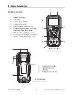
Page 9: ...green red LED 4 Rotary Function Switch 5 Function Buttons detailed below 6 Positive probe input jack for Voltage Capacitance Diode Continuity 7 COM negative probe input jack 8 Positive probe input jack for insulation resistance and earth bond resistance 1 Courtesy Work Lights 2 Test Probe Holders 3 Tilt Stand 4 Battery and Fuse Access Fig 4 1 Front View Fig 4 2 Rear View ...

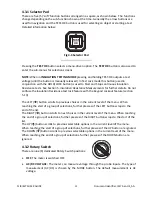
Page 10: ...odes see Section 5 5 Data Hold and Auto Hold Modes Press and hold for Keypad lockout mode see Section 5 13 Keypad Lockout In INSULATION TESTING MODE this button will serve to enable the test lock function for continuous insulation resistance testing See Section 5 7 Insulation Resistance Measurements for further information Use this Selector Pad to start stop Insulation Resistance Tests to enable e...

Page 11: ...istance test lock feature with the Keypad Lockout feature section 5 13 The LEFT button scrolls to previous choices in the current level of the menu When reaching the start of a group of selections further presses of the LEFT button wraps to the end of the list The RIGHT button scrolls to next choices in the current level of the menu When reaching the end of a group of selections further presses of...

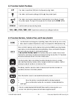
Page 12: ...hrough the Zero Ω Insulation and COM probe inputs 250V The meter can source a 250VDC TEST Voltage and measure Insulation Resistance through the Zero Ω Insulation and COM probe inputs 500V The meter can source 500VDC TEST Voltage and measure Insulation Resistance through the Zero Ω Insulation and COM probe inputs 1000V The meter can source 1000VDC TEST Voltage and measure Insulation Resistance thro...

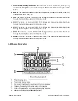
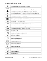
Page 13: ... Indicates that the meter is in locked mode Memory icon shown with the active memory location 1 99 Indicates the battery voltage status APO Indicates that the auto power off function is enabled Indicates that the meter is measuring AC voltage Indicates that the meter is measuring DC voltage Analog bar graph VFD variable frequency drive mode icon Frequency mode icon Earth Bond Resistance icon INSUL...

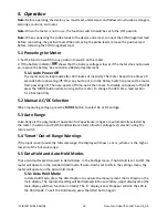
Page 14: ...ower off APO press the MODE button while turning on the meter To change the APO time read section 5 12 6 Setup Utility 5 2 Manual AC DC Selection When measuring voltage press the MODE button to select AC or DC voltage 5 3 Auto Range Auto Range is the only mode of operation for Capacitance ranges are automatically selected by the meter Insulation and Earth Bond Resistance tests allow for voltage te...

Page 15: ...on Resistance Function mode as described in section 5 12 1 Selecting modes 4 During the Test the insulation voltage will appear in the secondary upper reading area The resistance will be shown in the main reading area 5 Press TEST OK to start test 6 To lock the test for continuous testing press the HOLD LOCK button lock icon will appear and then press TEST OK to test continuously 7 The TEST icon o...

Page 16: ...re standard resistance to 40kohms NOTE The 99 point Data Record memory function cannot be activated in the usual way while using the Earth Bond Resistance function since the TEST OK button is used for testing in this case and not for saving readings The last reading however is held on the display and can then be saved as described in the Extended Functionality section below under Section 5 12 8 Da...

Page 17: ...devices under test during a measurement Injury to persons can occur 1 Set the function switch to the position 2 Use the MODE button to select the capacitance measurement The F Farad unit will be displayed 3 Insert the black probe lead into the COM negative terminal and the red probe lead into the positive terminal 4 Touch the tips of the probe across the part under test 5 Read the capacitance valu...

Page 18: ...options Auto power off indicated by the text APO A mode where the time period after which the meter enters sleep mode can be set The range is 1 to 30 minutes or OFF The factory default is 10 minutes Auto backlight off indicated by the text b Lit A mode where the time period after which the backlight turns off can be set The range is 1 to 30 minutes or OFF The factory default is 5 minutes Continuit...

Page 19: ...Do not confuse Lockout mode with the test lock feature used for continuous Insulation Resistance testing see Section 5 7 Insulation Resistance Measurements 5 14 Streaming Measurement Data using Bluetooth 5 14 1 General Some IR cameras from FLIR Systems support Bluetooth communication and to those cameras you can stream measurement data from the meter The data is then merged into the resultant tabl...

Page 20: ...f before it displays an out of tolerance voltage 1 To avoid electrical shock disconnect the meter if connected to a circuit remove the probe from the terminals and set the function switch to the OFF position before attempting to replace the batteries 2 Unscrew and remove the battery compartment cover 3 Replace the six standard AAA batteries observing correct polarity 4 Secure the battery compartme...

Page 21: ...sistance tests with new alkaline batteries These are standard tests of 1MΩ with a duty cycle of 5 seconds ON and 25 seconds OFF This does not include Bluetooth or Backlight use Auto Power Off APO User programmable OFF to 30 minutes in 1 minute increments with audible pre alert 20 seconds Measurement Types True RMS AC Volts DC Volts Earth Bond Resistance Insulation Resistance Capacitance Diode and ...

Page 22: ...3 F 18 C to 28 C and less than 75 RH Function Range Resolution Accuracy of Reading DC Voltage 1000 0V 0 1V 0 1 5 digits AC Voltage 1000 0V 0 1V 50Hz 60Hz 1 5 5 digits 61Hz 500Hz 2 0 5 digits VFD AC Voltage 1000 0V 0 1V 50Hz 60Hz 1 5 5 digits 61Hz 500Hz 5 0 5 digits Notes 1 Measurement start voltage 50V add 20 digits for accuracy 2 VFD LPF Cutoff 800Hz 3dB point 3 Input Impedance 3MΩ less than 100p...

Page 23: ...default is 30Ω Continuity MAX Test Current 1mA Continuity MAX Open Circuit Voltage 3 0V Diode MAX Test Current 1mA Diode MAX Open Circuit Voltage 3 0V Overload Protection 1000V AC rms or DC Function Range Resolution Accuracy of Reading Capacitance 1000 µF 1µF 1 2 2 digits 10 00mF 0 01mF 1 2 20 digits Notes 1 Overload Protection 1000V AC rms or DC Function Range Resolution Accuracy of Reading Frequ...

Page 24: ...sistance 50V 50kΩ 50 0MΩ 100V 100kΩ 100 0MΩ 250V 250kΩ 250 0MΩ 500V 500kΩ 500 0MΩ 100V 1MΩ 20GΩ Notes 1 Test Current 1 mA 2 Test Voltage Accuracy 0 20 Short Circuit Test Current 1mA nominal 3 Auto Discharge Function Discharge time 1 second for Cap 1µF 4 Max Capacitive Load Operable with up to 1µF load 5 Live Circuit Detection If 2V AC DC detected test inhibited 7 3 Input Specifications Function Ma...

Page 25: ... Warranty are MR7x CM7x CM8x DM9x IM7x and VP5x not including accessories which may have their own warranty 3 WARRANTY PERIODS For purposes of the The Limited Lifetime Warranty Lifetime is defined as seven years 7 after the product is no longer manufactured or ten years 10 from date of purchase whichever is greater This Warranty is only applicable to the original owner of the Products Any Product ...

Page 26: ...http www flir com to request an evaluation and obtain an RMA Purchaser is solely responsible for complying with all RMA instructions provided by FLIR including but not limited to adequately packaging the Product for shipment to FLIR and for all packaging and shipping costs Upon receipt of an authorized non warranty return FLIR will evaluate the Product and contact Purchaser regarding the feasibili...

Page 27: ...ACEMENT To be eligible for warranty repair or replacement Purchaser must notify FLIR within thirty 30 days of discovering of any apparent defect in materials or workmanship Before Purchaser may return a Product for warranty service or repair Purchaser must first obtain a returned material authorization RMA number from FLIR To obtain the RMA number Owner must provide an original proof of purchase F...

Page 28: ... 97070 USA Telephone 1 503 498 3547 Customer Support Technical Support Website http support flir com Technical Support Email T MSupport flir com Service and Repair Email Repair flir com Customer Support Telephone 1 855 499 3662 toll free Publication Identification No IM75 en US Release version AA Release Date 2014 August Language en US ...

Reviews: