FLIR
DM92
USER
GUIDE
Document
Identifier:
DM92
‐
en
‐
US_AB
16
5.
Read
the
capacitance
value
on
the
display.
Note:
For
very
large
capacitance
values,
it
may
take
several
minutes
for
the
measurement
to
settle
and
the
final
reading
to
stabilize.
5.9
Type
K
Temperature
Measurements
1.
Set
the
function
to
the
position.
2.
Use
the
button
to
select
temperature
measurement.
The
°F
or
°C
unit
will
be
displayed.
3.
While
observing
the
polarity,
insert
the
thermocouple
adapter
into
the
negative
COM
terminal
and
the
positive
terminal.
4.
Touch
the
tip
of
the
thermocouple
to
the
part
under
test.
Keep
the
thermocouple
tip
on
the
part
until
the
reading
on
the
display
stabilizes.
5.
Read
the
temperature
value
on
the
display.
6.
To
avoid
electrical
shock,
disconnect
the
thermocouple
adapter
before
turning
the
function
switch
to
another
position.
5.10
Current
Measurements
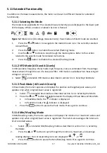
Current
is
measured
by
disconnecting
the
part
under
test
and
connecting
the
probe
leads
in
series
with
the
part,
see
Figure
5.1.
Figure
5.1
Disconnected
component
1.
Set
the
function
switch
to
the
position.
2.
Insert
the
black
probe
lead
into
the
negative
COM
terminal
and
the
red
probe
lead
into
one
of
the
following
positive
terminals:
A
for
high
current
measurements.
mA
for
low
current
measurements.
3.
Use
the
button
to
select
AC,
DC,
or
AC
+
DC
voltage
measurement.
The
indicator
will
be
displayed
for
AC
measurements.
The
indicator
will
be
displayed
for
DC
measurements.
The
indicator
will
be
displayed
for
AC
+
DC
measurements.
4.
Connect
the
probe
leads
in
series
with
the
part
in
accordance
with
Figure
5.1.
5.
Read
the
current
value
on
the
display.

