background image

Examine the Eachine ATX03 video transmitter and identify the red and black pair of wires that 
terminate in a 2-pin connector and the set of red, black, and yellow wires that terminate in a 
3-pin connector.  The red and black pair is use to power the vtx and will be directly soldered to 
the flight controller.  The red, black, and yellow set of wires are power and ground to the camera 
and video out of the camera to the video transmitter. 
 
Cut the connector off the red, black, and yellow set of wires.  Measure and cut the red and black 
wires to about 60mm and the yellow wire to about 40mm.  Strip and tin the three wires.  Solder 
the red wire from the vtx to the power pad on the camera.  This is the pad on the camera you 
removed the red wire from earlier.  Repeat for the black wire, soldering it to the pad that you 
removed the black wire from earlier.   


If you’ve forgotten which pad on the camera is for which wire, refer to the photograph.  When 
looking at the back of the camera, with the microphone on top, the red wire should be soldered 
to the left of the yellow wire and the black wire to the right of the yellow wire.  The pad which 
previous held the white wire will not be used.  The yellow wire in the middle should still be in 
place. 
 
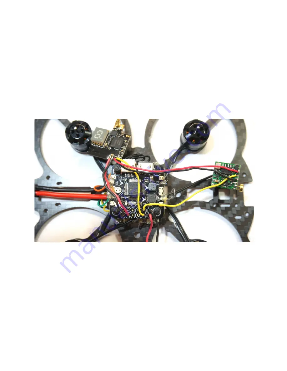
Next we will connect the video transmitter to the flight controller.  Cut the connector off the red 
and black pair of wires, trim to length, and strip and tin the ends.  Tin the +5v and GND pin 
holes on the flight controller’s pin rail and solder the red wire to the +5v pin hole and the black 
wire to the GND pin hole. 
 
Finally, solder the yellow video out wire of the video transmitter to the Vout pin hole and the 
yellow video from the camera to the Vin pin hole. 

Summary of Contents for Mini Owl

Page 1: ...eceiver The instructions also include the installation of an optional Pololu voltage regulator The Mini Owl can be built as a pusher motors upside down or a standard motors right side up quadcopter We...

Page 2: ...all four screws Leave the motor leads full length for now we ll trim them when we solder them to the ESC Next install the nylon screws by pushing them through the 20x20 holes from the bottom of the fr...

Page 3: ...1 ESC Be careful not to touch the nylon center screws with your soldering iron as they easily melt Finally locate the wiring harness that comes with the 4 in 1 ESC The wiring harness consist of six wi...

Page 4: ...wire to the appropriate pads on the ESC Note that the motor layout and ESC pad orientation aren t consistently named Specifically motor 3 will be soldered to pads A4 B4 and C4 Motor 4 will be soldered...

Page 5: ...B port and the directional arrow which indicates the front Turn the flight controller over and solder the power leads that you soldered to the battery leads in Step 3 to the B and B pads on the bottom...

Page 6: ...tors as follows Motor Position ESC Pads Servo wire color 1 Right rear A1 B1 C1 Green 2 Right front A2 B2 C2 Yellow 3 Left rear A4 B4 C4 Orange 4 Left front A3 B3 C3 Blue Route the servo wires under th...

Page 7: ...Identify the three pin holes on the Pololu When looking at the front the side with the components and with the pin holes on the bottom the pin holes are from left to right Vin GND and Vout Tin each pi...

Page 8: ...W Switchable FPV Transmitter We will be routing the video signal through the Omnibus Mini F3 flight controller to take advantage of its OSD capability Examine the back of the Diatone 600TVL camera and...

Page 9: ...ier Repeat for the black wire soldering it to the pad that you removed the black wire from earlier If you ve forgotten which pad on the camera is for which wire refer to the photograph When looking at...

Page 10: ...er and place it between the ESC and flight controller ensuring the diversity antennae are clear of the prop path Plug the connector into the Spektrum port on the flight controller If you are using a F...

Page 11: ...read them into the 3D printed bracket and tighten over the VTX This will secure the entire center stack and also facilitate easy removal of the top plate Install the flexible mini camera adjustable mo...

Page 12: ...tery strap into whichever slots you prefer to use to secure your battery Install the top frame plate onto the standoffs Go back and install all motor screws using blue Loc tite for security The Mini O...

Reviews: