background image

20

K 2 . 1

9. Adjusting 

units

9.1. ADJUSTMENT WITH CI60

CAUTION!

 The unit's air supply 

MUST be adjusted before the 

unit is used for the first time. This 

should be done in accordance with 

the projection documents. Adjust 

the values based on the projected 

values.

i

9.1.1. Adjustment

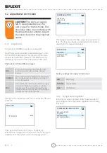
Only stage 2 (NORMAL) needs to be adjusted. Stages 

DQGKDYHȴ[HGVHWWLQJVZKLOHVWDJHKDVWREH

adjusted as required in the individual home.

7KHIXQFWLRQRIWKHGL΍HUHQWVWDJHV

MIN

Must not be used when the home is in use. 

0XVWQRWEHXVHGLQWKHȴUVWWZRKHDWLQJ

seasons.

NORMAL

Used under normal conditions. On this setting 

the air supply must be adjusted according to 

current regulations. 

MAX

Used if there is a need for increased air supply 

on account of higher occupancy or a raised 

humidity level, for example during showering 

or when clothes are being dried. This setting is 

normally used for limited periods.

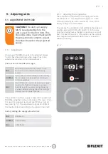
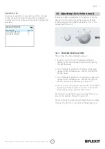
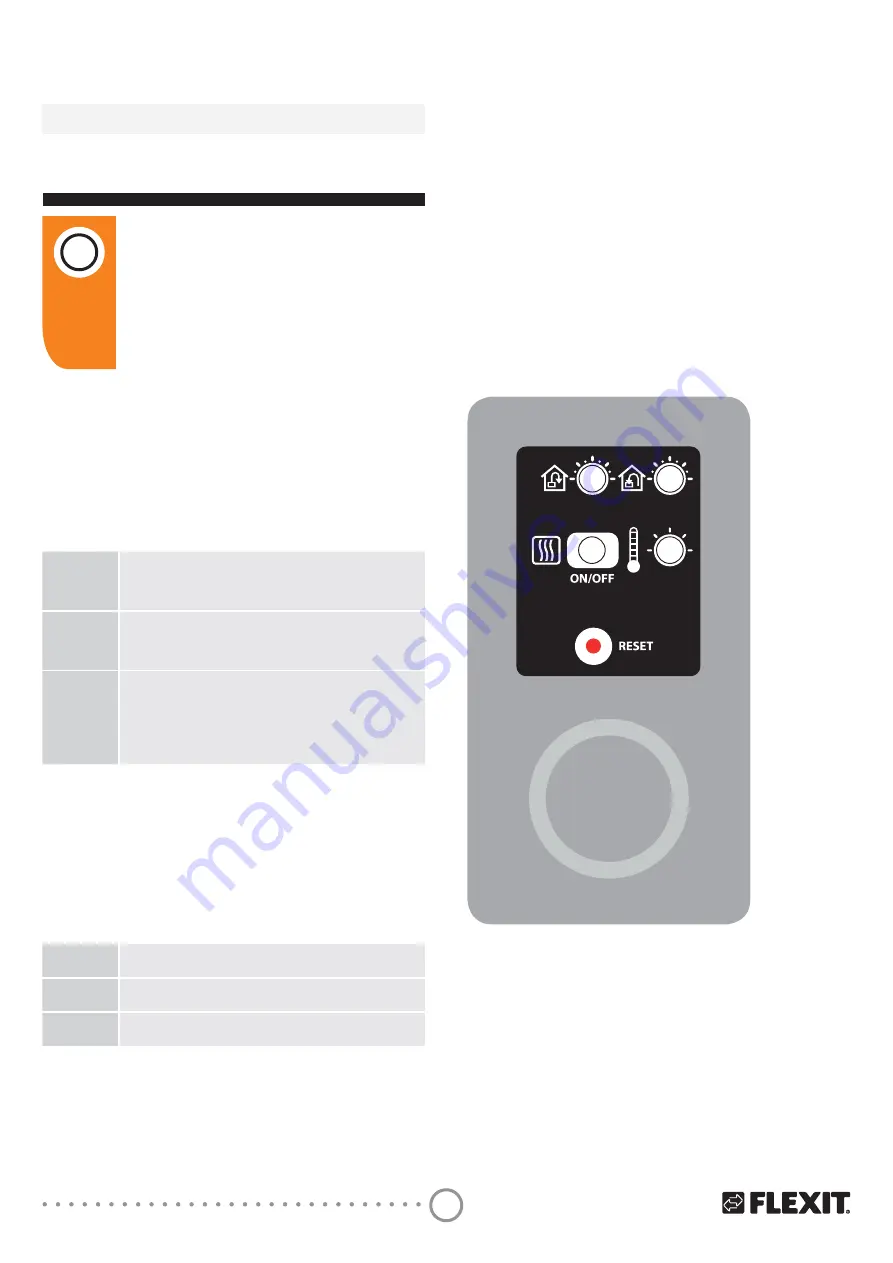
The ventilation unit’s air supply is adjusted in speed level 

NORMAL using the knobs on the back of the cover. Knob 

9 is used for supply air level and knob 8 for extract air 

level (see Fig. 13). The adjustment range is 20-100% of 

the maximum level according to the scale on the knob. 

Factory settings for supply air/extract air:

MIN

ȴ[HG

NORMAL

75% (variable)

MAX

ȴ[HG

9.1.2.  Adjusting the temperature

The temperature required for the supply air can be 

set with knob 11. The adjustment range is 10 - 30°C. 

It should normally be set to around 18°C. Use of the 

factory setting is recommended.

If necessary, the ventilation unit’s additional heating can 

also be switched ON/OFF with switch 10. In this case 

only the rotating heat exchanger is used as a source of 

heat. It is best to leave it in ON position, as the unit will 

then respond automatically when there is a need for 

additional heating. 

)LJ

8

9

10

11

Summary of Contents for K2.1

Page 1: ...TALLATION INSTRUCTIONS Air handling unit with kitchen hood and control automation ART NO 700114 700116 700118 700119 700122 700123 700124 700126 111140EN 14 2019 10 Flexit K2 1 INSTALLATION INSTRUCTIO...

Page 2: ...2 K 2 1...

Page 3: ...Dimensioned drawings 14 7 Capacity and sound data 15 7 1 Supply air side 15 7 2 Extract air side 15 7 3 Correction factor for Lw 16 8 Installation of control panel CI 60 600 17 8 1 Content 17 8 2 Inst...

Page 4: ...tract air from kitchen INFO When a text box is this FRORXU LWbPHDQV WKDW LW FRQWDLQV important information i CAUTION When a text box is this colour it means that material damage may be the consequence...

Page 5: ...be carried out by qualified electricians If the power lead is damaged it must be replaced by the manufacturer the manufacturer s service agent or a similarly qualified person The unit must not be use...

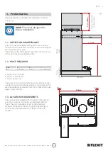
Page 6: ...front of unit B Space at side of unit C Space above unit These are minimum requirements and only take service needs into account National statutory requirements for electrical safety may deviate from...

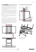
Page 7: ...PRXQWLQJ WKH LQFOXGHG ZDOO EUDFNHW HG WR the unit is used The unit must not be placed on a wall with rooms on the other side which are sensitive to noise The wall must be sound insulated If necessary...

Page 8: ...wall must have good sound insulation see chap 1 4 Recommended sound attenuation for wall mounting at page 7 7KH ZDOO PXVW EH FRPSOHWHO DW EHKLQG WKH YHQWLODWLRQ unit If the kitchen hood area is tiled...

Page 9: ...9 K 2 1 LJ 596 mm B 2mm B 2mm LJ 2 2 ENCASING The casing must not be deeper than dimension A A...

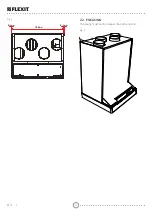
Page 10: ...on well up to the unit To avoid condensation it is very important for the outdoor air duct and the exhaust air duct to have LQVXODWLRQ DQG D SODVWLF PX SXOOHG ULJKW GRZQ WR WKH unit NB Use tape to sea...

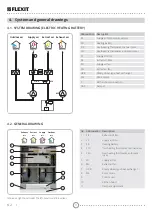
Page 11: ...ng battery F10 Overheating thermostat manual reset F20 Overheating thermostat automatic reset FI1 6XSSO DLU OWHU FI2 WUDFW DLU OWHU M1 Supply air fan M2 Extract air fan HR R Rotary wheel type heat exc...

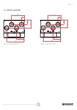
Page 12: ...12 K 2 1 6KRZQ DV D ULJKW KDQG PRGHO 6KRZQ DV D OHIW KDQG PRGHO 514 227 371 84 129 229 514 227 371 84 129 229 4 3 NIPPLE LOCATION...

Page 13: ...IP21 Filter class ePM1 55 F7 Filter type supply air extract air RPSDFW OWHU Filter dimensions WxHxD 130 x 335 x 50 mm Weight 57 kg Duct connection 125 mm sleeve Height 700 mm Width 598 mm Depth 510 m...

Page 14: ...14 K 2 1 6 Dimensioned drawings Dimensions in mm...

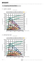
Page 15: ...65dB A 55dB A 50dB A 100 80 60 40 6 3 0 100 200 300 400 60 60 100 dB A 80 0 200 400 600 800 0 40 20 3RZHU RQVXPSWLRQ W LU RZ UDWH O s RQWDFW UHVLVWDQFH Pa LU RZ UDWH m h 100 80 40 55dB A 60dB A 50dB...

Page 16: ...he unit in LwA At the bottom right of the table a total value for radiated sound from the unit is stated in LwA This is an aggregate value The values for the radiated sound IRU WKH GL HUHQW RFWDYHV KD...

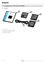
Page 17: ...Installation of control panel CI 60 600 8 1 CONTENT 1 2 3 4 5 1 Control panel 2 Back piece for concealed installation 3 Back piece for surface installation 4 Installation instructions 5 Cable for con...

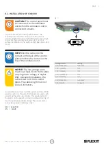
Page 18: ...urface installation on the wall use high back piece item no 3 INFO Click the cable into the contact at the back of the control panel and into the contact on the top of the ventilation unit i NOTICE Th...

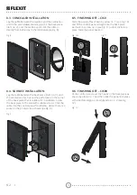
Page 19: ...suitable for installation Screw the back piece to the wall with suitable screws Click the cable into the control panel from below where there is a socket in the printed circuit board se Fig 9 LJ J 8...

Page 20: ...during showering or when clothes are being dried This setting is normally used for limited periods The ventilation unit s air supply is adjusted in speed level NORMAL using the knobs on the back of th...

Page 21: ...increased air supply on account of higher occupancy or a raised humidity level for example during showering or when clothes are being dried This setting is normally used for limited periods First go t...

Page 22: ...on options 1 Switch on front of unit This gives a half open damper which will increase the air volume passing through the hood 2 Turn the knob to position 2 This gives a fully open damper which will a...

Page 23: ...1 FORCED VENTILATION FLEXIT K2 1 Max air volume through kitchen hood in case of forced air volume Measurements have been taken at 2 3 pressure in the extract air duct and 1 3 pressure in the exhaust a...

Page 24: ...is very important the GXFWV IURP WKH XQLW DUH DOVR H HFWLYHO LQVXODWHG VR that no condensation forms on or in the ducts It is especially important to check this if the ducts are to be boxed in XFWV D...

Page 25: ...s are consumables Our products are subject to continuous development and we therefore reserve the right to make changes We also disclaim liability for any printing errors that PD bRFFXU 15 Waste handl...

Page 26: ...rective 1907 2006 EC REACH Regulation Our products have been tested in accordance with parts of 2006 42 EC Machine Directive Safety Producer FLEXIT AS Televeien 15 1870 rje Norway Type K2 1 Ventilatio...

Page 27: ...27 K 2 1...

Page 28: ...Flexit AS Televeien 15 N 1870 rje www flexit no...

Reviews: