18 Outputs
FLUXUS ADM 8027, F801, ADM 8127B
UMFLUXUS_F8V4-6-1EN, 2018-10-10
121
18
Outputs
If the transmitter is equipped with outputs, they have to be installed and activated before they can be used:
• assign a measuring channel (source channel) to the output (if the transmitter has more than one measuring channel)
• assign the physical quantity (source item) to be transmitted to the output by the source channel, and the properties of the
signal
• define the behavior of the output in case no valid measured values are available
• activation of the installed output in the program branch
Output Options
18.1
Installation of an Output
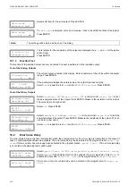
All outputs are installed in
Special Funct.\SYSTEM settings
\
Proc. outputs
.
The source items and their scroll lists are described in Tab. 18.1.
Note!
The settings will be stored at the end of the dialog. If the menu item is quit by pressing key BRK, the
changes will not be stored.
Select
Special Funct.
\
SYSTEM settings
\
Proc. outputs
. Press ENTER.
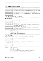
Select the output to be installed. Press ENTER.
The scroll list contains all actually available outputs. A tick (
) after a list item indicates that
this output has already been installed.
This display will be indicated if the output has not been installed yet. Select
yes
. Press EN-
TER.
If the output has already been installed, select
no
to reconfigure it or
yes
to uninstall the
output and to return to the previous menu item in order to select another output. Press EN-
TER.
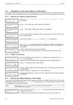
Select in the scroll list the measuring channel to be assigned to the output as the source
channel. Press ENTER.
This display will not be indicated if the transmitter has only one measuring channel.
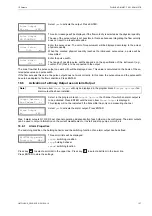
Select a physical quantity (source item) to be transmitted to the output by the source chan-
nel.
If a binary output is configured, only the list items
Limit
and
Pulse
will be displayed.
Tab. 18.1: Configuration of the outputs
source item
list item
output
Measuring value
physical quantity selected in the program branch
Output Op-
tions
Quantity
Q+
totalizer for the positive flow direction
Q-
totalizer for the negative flow direction
Σ
Q
sum of the totalizers (positive and negative flow direction)
Limit
R1
limit message (alarm output R1)
R2
limit message (alarm output R2)
R3
limit message (alarm output R3)
Pulse
from abs(x)
pulse without sign consideration
from x > 0
pulse for positive measured values
from x < 0
pulse for negative measured values
SYSTEM settings
↕
Proc. outputs
Install Output
↕
Current I1
(
)
I1 enable
no
>YES<
I1 disable
>NO<
yes
I1 Source chan.
↕
Channel A:
Source item
↕
Measuring value


