EN
INSTRUCTIONS MANUAL
PLEASE RETAIN FOR FUTURE REFERENCE
Name
Function
Model / Type
Serial number
Year of manufacture
Manual Revision
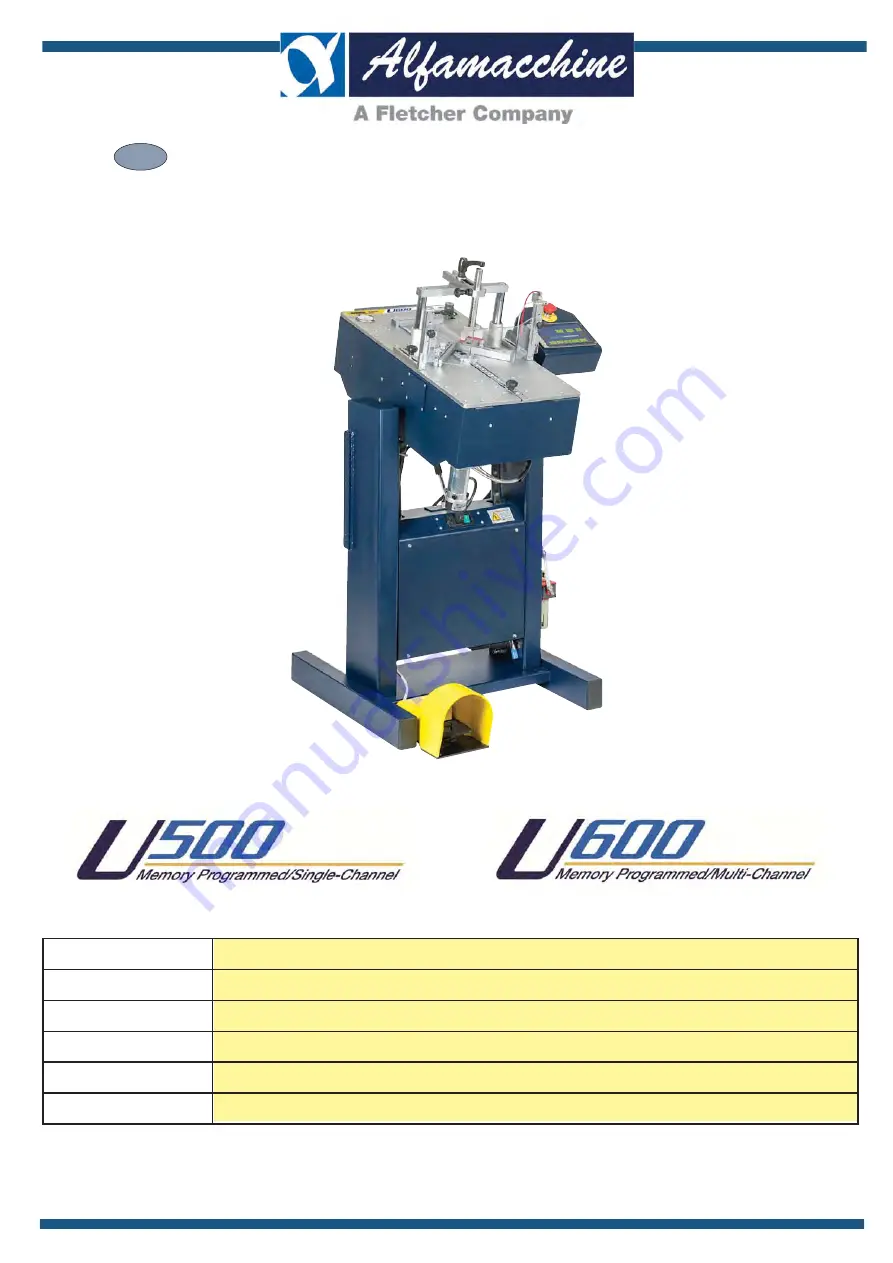
FRAME ASSEMBLING MACHINE
ASSEMBLY OF FRAMES BY INSERTION OF METAL V-NAILS
U500-U600
(previous version MP - MC)
02
Page 1: ...L PLEASE RETAIN FOR FUTURE REFERENCE Name Function Model Type Serial number Year of manufacture Manual Revision FRAME ASSEMBLING MACHINE ASSEMBLY OF FRAMES BY INSERTION OF METAL V NAILS U500 U600 prev...
Page 2: ...MACHINE Funzione Purpose ASSEMBLY OF WOODEN AND SYNTHETIC MDF MOULDINGS USING METAL V NAILS Modello Model Name U500 Tipo Type ELECTRO PNEUMATIC Numero di Serie Serial Number E CONFORME ALLE DISPOSIZI...
Page 3: ...MACHINE Funzione Purpose ASSEMBLY OF WOODEN AND SYNTHETIC MDF MOULDINGS USING METAL V NAILS Modello Model Name U600 Tipo Type ELECTRO PNEUMATIC Numero di Serie Serial Number E CONFORME ALLE DISPOSIZIO...
Page 4: ...TRANSLATION OF THE ORIGINAL INSTRUCTIONS Keep for future reference Codice Documento Rev Data di salvataggio Data di stampa U500 U600 ISTRUZIONI 02 04 11 2015 04 11 2015 EN 4...
Page 5: ...AND ALARMS 27 4 2 1 COMMAND AND SIGNALLING ACTUATORS 27 4 2 2 START UP FUNCTIONS 28 4 2 3 STOP FUNCTIONS TIMED AND SAFETY STOPS 28 4 3 CHECKS ADJUSTMENTS AND START UP 29 4 4 START UP 29 4 4 1 CHECKS...
Page 6: ...YINAPPROPRIATE MANNER 1 INTRODUCTION TO USE 1 1 HOW TO CONSULT THIS MANUAL AND THE SYMBOLS ADOPTED Please pay particular attention to the words DANGER WARNING DANGER CAUTION and NOTES as used in this...
Page 7: ...ks The operator must have the same skills in terms of safety as the maintenance technicians and adequate professional competence During its PERMITTEDAND REASONABLY PREDICTABLE USE the machine may be u...
Page 8: ...onal in this instruction manual beforehand elements have come to a complete standstill j as indicated in this manual outdoors or worksites with open windows and doors processing of materials and produ...
Page 9: ...istance between V nails 145mm 5 3 4 V nail magazine capacity U600 1100pz 1100pcs Max quantity of V nails inserted per position 9pcs V Nail insertion positions Multiple Max distance between V nails 145...
Page 10: ...st be made up of wooden mouldings of various hardness with multiple surface The main technical characteristics of the products handled by the machine described herein are provided below DESCRIPTION OF...
Page 11: ...ety clothing Residual risk caused by piloting the valves with a special tool There is a residual risk for the maintenance technician when the safety guards are open and valve piloting is activated usi...
Page 12: ...he electrical enclosures operating tests which require interventions with the electrical equipment powered and or with the guards removed j the aforementioned components Furthermore interventions whic...
Page 13: ...R ATTEMPT TO VOLUNTARILY CIRCUMVENT A FIXED GUARD operator ever attempt to voluntarily circumvent a moveable guard meticulously and carefully to the indications provided in the installation use and ma...
Page 14: ...orresponding to the different types and dimensions of the frames being made can be stored in the machine s memory use special Alfagraf V nails with Pulling Power effect or standard V nails 1 working b...
Page 15: ...ing on the nailing head installed When the size of the V nails is changed the nailing head must also be switched over to match the V nails used The V nails are held in position by the V nail pusher de...
Page 16: ...ic cylinders C handle for installation of the unit on the support D handle for locking cylinder forward back movement E handle for locking the cylinder stem F screw for locking cylinder up down moveme...
Page 17: ...one used on the U500 machine P different for each typ of V nail and the one used on the U600 machine with magazine L which is for all V nail heights On the U500 machine the head is marked with a numbe...
Page 18: ...the table below 4 Do not allow corrosive substances to come into contact with the machine 5 Check that the pack has not been damaged and that it is perfectly dry including rain snow and hail and it mu...
Page 19: ...t data and the order Technical check 1 Condition and intactness of packaging 2 Check that the packaging shows no signs of visible damage caused during transport and handling operations All the above c...
Page 20: ...ed for installation procedures moves out of the way Lifting FROM BELOW The operations to lift and handle the machine must be carried out of the chosen equipment are inserted correctly under the packag...
Page 21: ...ight of the machine indicated on the packaging falls within the maximum hoisting capacity of the chosen lifting equipment DANGER CAUTION Do not rig the machine up with belts for handling operations Wh...
Page 22: ...ALLOW FOR EASY REMOVAL OF THE MACHINE FOR MAINTENANCE it must be positioned in a place having the surface 3 2 LEVELLING THE MACHINE falling or uncontrolled displacement In order to avoid mechanical s...
Page 23: ...bench and the extensions so that the lower surface of the mouldings rest fully on the entire support surface when the double stopper presses down on the ends of the mouldings To install the extensions...
Page 24: ...ws B which act as plugs 3 Remove the two screws from the special support 4 Insert the two screws A Tilt the console to meet operating requirements as illustrated in the example and insert the two scre...
Page 25: ...nd the legislative and regulatory provisions in force in the country of installation 4 The electrical enclosure power supply cable outside the machine casing must be routed through the spaces prepared...
Page 26: ...carried out without the risk of electric shock or burns a disconnect device has been installed for the electrical equipment The power supply disconnect device as can be seen in the power circuit diag...
Page 27: ...urs in order to restore the original characteristics of the capacitors For this purpose supply power to the input terminals without applying the load on the output terminals After performing this prep...
Page 28: ...compressed air isolation device as can be seen in the pneumatic diagram supplied with the machine is supplied for the sole source normal conditions of use PNEUMATIC SUPPLY ISOLATOR DEVICE The unit is...
Page 29: ...cated on the control panels Apart from normal machine operation the operator must also start and stop the machine in normal conditions and stop it in emergency conditions The operator must also carry...
Page 30: ...eep for future reference Codice Documento Rev Data di salvataggio Data di stampa U500 U600 ISTRUZIONI 02 04 11 2015 04 11 2015 EN 26 A the V nail magazine B vertical blocking D horizontal locking B C...
Page 31: ...play B Electrical enclosure control panel with power socket and start switch C Pedal switch PEDAL SWITCH given during installation see the heading Customizations Normally pressing the pedal switch sta...
Page 32: ...r switch to ON I 1 _ Check the emergency devices and reset any which have been tripped 2 _ Wait for the operating system to boot 3 _ Zero the machine by touching the ZERO button and then the START and...
Page 33: ...e the machine to shutdown in a Category 0 stop The intervention of one of these protection devices is caused by an overcurrent that may be an overload or a short circuit STOP DUE TO THE MAIN CUT OFF D...
Page 34: ...appear if any alarm conditions are present e g no air pressure or safety guards open DESCRIPTION OF THE HOME PAGE CONTROLS Touch the ZERO button to complete the resetting sequence and go to the main p...
Page 35: ...ting mode J Head direction K V Nail insertion and type L Eliminates V nail initialises program M Head direction N Scale mm inches O Moulding max reference dimension P V Nails positioning and type READ...
Page 36: ...ivate any other manual controls During the assembly cycle the touch screen is disenabled 4 4 2 PRODUCTION PROGRAMMING PARAMETERS SETUP j which the machine operator can carry out during the production...
Page 37: ...utside corner from the inside corner Program copy search select a program from the list and touch the button to copy it Press on the USB icon to save the selected program on CALL UP A PROGRAM Several...
Page 38: ...earch character has been entered displaying all the names containing the characters entered on the keypad to the work page CREATE A NEW PROGRAM mouldings the number and type of V Nails to be inserted...
Page 39: ...llows 1 Move the head by touching the direction arrows until you reach the desired moulding size 2 Touch the part that indicates the current head position to set the new position using the numeric key...
Page 40: ...number will be shown Eliminating the V nail position Multiple V nails per position the V nail selection insertion icon for at least 2 seconds Select the V nail colour from the menu and then touch the...
Page 41: ...access the speed menu Choosing the correct speed depends on the hardness of the material wood plastic MDF and the sharpness of the V nail used The harder the material the less sharp the V nail should...
Page 42: ...sure that the correct number of sides is selected for the frame counter to work properly CAUTION All changes made to the program are immediately saved Selecting the pressure of the clamping system CAP...
Page 43: ...ge MAINTENANCE CONTROLS PAGE SERVICING HEAD In Out hammer activation control Control to open close the V nail pusher cylinder in the magazine U600 model only Control to lock release the V nail magazin...
Page 44: ...he V nail pusher cylinder is opened 3 Put the V nails in the magazine B taking care to make sure the sharp part glue edge side is facing upwards 4 Turn the PLV valve back to the initial position CAUTI...
Page 45: ...es the slot in the magazine V nail height is indicated on each magazine slot B 3 Put the V nails in the magazine C making sure the sharp part glue edge side is facing upwards and the top of the stick...
Page 46: ...marked adapters F depending on the V Nail height required 5 7 10 12 and insert it in the magazine D Secure in place with the special screws C 5 Repeat the previous operations to modify the other V nai...
Page 47: ...the hammer in the high position is aligned with the magazine D There must be no play between the hammer and the magazine 6 Remove the alignment fences from the working bench E to free the holes below...
Page 48: ...f the mouldings or outside of the corner act on the knobs to close them The mouldings may have an outer edge which slants slightly To achieve better contact between these mouldings the slant along edg...
Page 49: ...orner is narrow and you wish to use one cylinder only close the handle on the cylinder you wish to block B In this way the stem remains stationary 4 If the frame is wide loosen the knob on the cylinde...
Page 50: ...r insertion 1 Loosen the locking handle on the vertical clamp unit A and lift it out 2 Insert and position the single vertical clamp unit securing it in place by tightening the locking handle B Single...
Page 51: ...c stopper holder Installe the stopper A for the required hardness in the stopper holder positioning it under the slot and manually pressing it in place To remove the stopper A simply pull it out with...
Page 52: ...pers during V nail insertion This pressure is shown on the pressure pressure gauge located on the top surface of the machine A 3 Select the most suitable pressure values for the materials being handle...
Page 53: ...ored in the work program The icon with two columns shows the set speed and pressure levels CAPS not activated regulator on the pneumatic panel The icon with 1 column shows the speed level Soft Clamp f...
Page 54: ...UGGESTIONS FOR MAKING PERFECT JOINS 1 V nail types j using a wide variety of materials different V nails are available with different degrees of sharpness suitable for use with different hardness valu...
Page 55: ...s The menu offers a choice of low level areas required for the machine U500 version C Barcode D Pressure regulation E Diagnostics F Customizable parameters G Counters U600l head adjustment hand I Cont...
Page 56: ...e program will automatically calculate the others mechanical stop be moved manually to the two positions to be acquired is in front of the L block support position 1 enters into the L block support se...
Page 57: ...2015 EN 53 UTILITY Most utilities can be accessed using a password Contact your Distributor or Service Centre to request the access codes Program Backup saving located on the side of the operator pane...
Page 58: ...to access the Production Record page 3 The production record page holds the daily production data depending on the last days setting Act on the UP and DOWN buttons to consult the whole register report...
Page 59: ...ed for In the event of replacing the control console with a new one or one with a different setup the technical assistance centre may be authorized to rest the machine model as long as the access code...
Page 60: ...nalling device refer to the Layout and description of the control and signalling devices given in the electrical diagram provided as an attachment to this manual Check the V Nail magazine is full and...
Page 61: ...ll controls on the touch screen are disenabled until the system has been reset j interrupts the production cycle underway 4 5 2 SWITCH OFF DANGER WARNING ALWAYS WAIT UNTIL THE MACHINE WORKING CYCLE HA...
Page 62: ...NICIAN DUTIES The maintenance technician duties are troubleshooting and the replacements of worn or damaged parts or structural elements The work zones that may present risks for the machine s mainten...
Page 63: ...reactivate all the safety devices Do not tamper with or deliberately damage the protective screens nor remove or conceal the warning notices In the event of deterioration or illegibility of the safet...
Page 64: ...st be observed to keep the machine in perfect working order 1 keep the machine clean and tidy 2 avoid all damage 3 avoid a situation wherein make shift or urgent repairs become commonplace 4 do not pe...
Page 65: ...e service Parts must always be replaced using original spare parts or at least parts which provide equivalent quality and safety Check their integrity both internally and externally and make sure ther...
Page 66: ...reserves the responsibility for the replacement interventions METHODS AND RESULTS Proceed to dismantle the hammer to replace the gaskets only or the whole piston as follows FREQUENCY Every 1 000 000...
Page 67: ...ducts and the wiring inside and outside the enclosures If these including single core and or multicore cables are not in perfect condition they must be replaced in order to ensure correct operation Ch...
Page 68: ...and power actuators Parts must always be replaced using original spare parts or at least parts which provide equivalent quality and safety THE INSTRUCTIONS CONCERNING THE REPLACEMENT ARE NOT GIVEN IN...
Page 69: ...used to clean glasses If the screen is very dirty you may also use a damp cloth with water or buy a special detergent solution suitable for removing greasy marks from the screen To avoid irreparably...
Page 70: ...s provided with each individual lubrication product used The lubrication operations which must be performed by maintenance technicians are indicated below To obtain high performance and faultless oper...
Page 71: ...neumatic actuators METHODS AND RESULTS Lubricate the carriage guides located under the working bench To gain access and perform lubrication the maintenance technician must 1 Isolate the machine from e...
Page 72: ...ons and the type of information the operator s will receive are described in chapters 3 and 4 Depending on the type of information action must be taken to eliminate the cause that led to generated the...
Page 73: ...ems PROBLEM FAULT Interruption of production from the pusher Faulty V nails Faulty or clogged valves Pedal valve or position valves blocked POSSIBLE SOLUTIONS 1 Check that the minimum pressure value f...
Page 74: ...N TO A POINT WHERE ANY FORM OF REPAIR WOULD NOT BE AN ECONOMICALLY VIABLE SOLUTION IT MUST BE PUT OUT OF SERVICE AND RENDERED INOPERATIVE AND FREE FROM ALL POTENTIAL HAZARDS Decommissioning of the mac...
Page 75: ...e that all plastics metal materials and electrical components which must be disposed of separately are duly sorted The employer must be aware of all the statutory legislation in force in the country o...
Page 76: ...66 21 63 1 3817 5 9 92 3 9 35 66267 72 5 63 1 3817 5 2 725 35 66 21 6 5929 92 1 52 0 57 772 91 77529 92 20 1 2 0 57 772 6 1 725 1 5 2 2 9 57 1 52 2 2 25 217 35 66267 72 5 2 2 35 66267 72 5 3527 21 9...
Page 77: ...25 217 35 66267 72 5 35 6 1 5 35 66267 72 5 3527 21 35 66267 72 5 2 6 5 72 2 175 7 5 2035 66 5 5 8 752 5 2 725 8 5 725 21 16 99 725 352 5 66 92 9 92 3527 21 9 92 2 2 5 2 725 35 66 21 2 9 77529 92 20...
Page 78: ...DFFKLQH VUO GGUHVV 7 3KRQH 0DLO 3URMHFW 36 8 8 UHDWHG E 5 8 9 57 03 1 56 25 217 03 1 5 0 1 5 35 662 6 7 6 7 8 5 35 662 6 7 036 35 662 6 7 6 5 72 2 5 35 6685 32 5 6833 5 5 8 0 1 5 35 6685 5 8 725 1 7 5...
Page 79: ...5 9 1 0 6 0 775 2 03 B GIW 6 7 OIDPDFFKLQH VUO ITALY 7 7 U500 MEMORY PROGRAM 0 5 1 6723 1 21752 2 1M5 2M5 3M5 4M5 5M5 6M5 C3 I3 6M3 5M3 4M3 3M3 2M3 1M3 C8 I8 1M1 blue 3M1 bwn 2M2 blk 7M2 sh 4M2 yel 3...
Page 80: ...k 7M2 sh 4M2 yel 3M2 gre 1M2 red J302 93 93 1 2 5 J201 J5 J6 J7 J3 J401 J400 S1H5 S2H7 S3H10 S4H12 S5H15 S3 H10 S4 H12 S5 H15 EK270 2 EK271 2 EK273 2 A A 1 86 1 86 S1 H5 S2 H7 J302 J201 J5 J6 J7 J3 J4...
Page 81: ...56 25 1 385326 7 287 7 35 66 3 50 66 21 2 7 5 7 55 0 1 65 6 12 5 9 1 0 6 0 775 2 0 B GIW 6 7 OIDPDFFKLQH VUO ITALY 7 7 H07 2 H08 3 0V 15 24V 9 INP6 10 H06 1 1 J6 EK271 1 J3 EK271 1 1 PNEUMAX 171E2N T...
Page 82: ...283 66 0 0217 2 58332 0 12 21 85 7 0 1 02725 5283 66 0 0217 2 58332 02725 0 12 7 0 1 6 5283 66 0 0217 2 58332 6 77 0 12 7 5283 66 0 0217 2 58332 7 67 7 02725 5283 66 0 0217 2 58332 02725 7 67 7 0 1 35...
Page 83: ...R RPPHQWL 4XDQWL W j 25 217 03 1 5 1 52 2 2 25 217 25 217 03 6833257 68332572 2 225 217 9 57 03 1 5 1 52 2 2 9 57 12 6 1 6 648 5 320 7 9 57 03 5283 66 0 58332 2 2 9 57 7 6 7 8 5 3527 7 21 203 7 3527 2...
Page 84: ...5 5 0 12 21 85 0 0 1 1 52 0 3 9 7 7 0 81 68332572 1 52 63 1 3 817 0 9 7 7 0 81 68332572 6 1625 0 68332572 7 5 7 2 63 1 3817 0 9 7 763 81 9 7 7 0 81 0 5 3527 21 0 12 0 9 7 763 81 3 675 1 17 7 029 0 0 6...
Page 85: ...4XDQWLWj 3 675 1 66 2 02725 0 12 0 3 675 6267 12 02725 0 12 0 3 675 03 1 0 9 7 763 81 521 69 6 7 21 5 35 6 86 1 772 6 56 67 1 86 1 772 38 0 0 67 03 1 02725 0 12 0 23 5 2 03 1 38 0 12 0 1 03 1 0 9 7 7...
Page 86: ...I 02 04 11 2015 04 11 2015 EN 82 1XPHUR RJJHWWR 2JJHWWR 7LWROR 4XDQWLWj 7 67 7 3267 5 25 6 77 0 203 7 721 2 1 98 2 1 68332572 8 6 1625 0 12 0 9 7 7 0 81 1 52 6 77 0 77 2 17 6 77 0 9 7 7 0 81 68332572...
Page 87: ...6 77 0 203 7 9 7 7 0 81 7 67 7 1 52 638 6 21 5 0 11 7 67 638 6 21 5 0 0 57 772 0 203 72 7 67 7 683 5 25 0 203 7 67 0 0 5 12 67 81 75 9 56 3267 5 25 58332 7 67 0 63 6625 75 9 56 17 5 25 0 2 2 98 2 1 03...
Page 88: ...81 23 5 2 38 2 533 03 0 9 7 9 7 63 1 5 81 521 38 2 26 03 0 86 1 772 6 56 3 512 7 1 1 0 68332572 2 2 7 1 1 0 68332572 7 6 255 92 7 1 1 0 03 5 12 67 81 1 17 7 533 0256 772 17 1 533 03 0 9 7 763 81 9 7 7...
Page 89: ...Y GUARD PROTEZIONE CE MAGAZZINO Alfamacchine 10 2015 U series TAB 8 FRONTAL CLAMP ASTA A FOGLIA BL ORIZZONTALE 1XPHUR RJJHWWR 2JJHWWR 7LWROR 4XDQWLW 3527 21 32 5 21 72 0 12 0 68332572 02 3527 21 0 12...
Page 90: ...6 25 3 6 3 6 25 2 3 6 3 6 25 8 75 9 56 233 2 7 0321 5 8 2 03 0 9 7 7 0 81 5 12 67 81 521 233 2 7 0321 5 8 2 0 1 0 Alfamacchine 10 2015 U series TAB 12 CE SAFETY GUARD PROTEZIONE CE 1XPHUR RJJHWWR 2JJH...
Page 91: ...ROR 4XDQWLWj 2 2 98 2 1 03 9 7 7 0 81 0256 772 17 1 533 03 0 9 7 763 81 63 1 3817 203 72 81 2 0 0 352 521 3 1 0 81 9 7 7 0 81 0 12 5 9 7 7 0 81 68332572 2 2 5 725 63 6625 03 2 2 98 2 1 03 0 68332572 2...
Page 92: ...03 9 7 7 81 23 5 2 38 2 533 03 0 521 38 2 26 03 0 86 1 772 6 56 68332572 7 6 255 92 7 1 1 0 03 1 17 7 533 0256 772 17 1 533 03 0 9 7 763 81 9 7 763 81 521 6 72 02725 0 03 86 1 772 6 56 23 5 2 02725 03...
Page 93: ...CTIONS Keep for future reference Codice Documento Rev Data di salvataggio Data di stampa U500 U600 ISTRUZIONI 02 04 11 2015 04 11 2015 EN 89 Alfamacchine 10 2015 U500 TAB 15A FLOOR STAND EXPLODED VIEW...
Page 94: ...TE TE M8x25 UNI 5739 ZB 1 46 810380438 TAPPO OVALE OVL40x20x1 3 1 47 352600057 SUPPORTO OVALE CASSETTA DISPLAY TOUCH MP MC 1 48 710100139 VITE TCEI M8x20 UNI 5931 8 8 Z B 1 49 291800040 NUOVO CAVALLET...
Page 95: ...ANNEX A INSTRUCTIONS MANUAL PLEASE RETAIN FOR FUTURE REFERENCE EN...
Page 96: ...4 MACHINE CUSTOMIZATION 6 Start option 7 7 Automatic head positioning 10 7 Setting the sequence of the mouldings blocking devices 14 8 Lock Program Editing setup 19 9 Zeroing commands 22 9 Automatic...
Page 97: ...5 C electrical equipment protection rating of at least IP54 j Equipment for machine designed for indoor installations Machine NOT suitable for operation in contaminated atmospheres for example dusts a...
Page 98: ...ltage dips must not exceed 20 of the peak voltage or for more than one cycle More than 1 second interruptions TECHNICAL CHARACTERISTIC TYPE ALTERNATE CURRENT POWER SUPPLY Nature of the current Rated c...
Page 99: ...unt a presumed short circuit current in the point of installation of kAsymmetrical see TECHNICAL CHARACTERISTIC TYPE RECOMMENDED OVERCURRENT PROTECTION DEVICE Rated insulation voltage Rated current Ma...
Page 100: ...sequence for the mouldings blocking and stapling cycle NORMAL keep the Pedal pressed down to run the mouldings blocking and stapling cycle If the operator takes his foot off the pedal before the cycl...
Page 101: ...ANUAL START ON FIRST RUN OFF 9 The FULLAUTO j start up from program changeover or after maintenance operations making it unnecessary for the user to intervene on the terminal GUI Automatic head positi...
Page 102: ...ing devices one after another at different times can be very useful in improving the perfect alignment of the frame before it is stapled j j V H 15 H V 16 0 17 Contact a Technical Service Centre or yo...
Page 103: ...04 11 2015 EN Zeroing commands 22 positions after maintenance operations or mechanical adjustments have been made j IMPORTANT MAGAZZINO TESTA Automatic head return 24 CUSTOMIZE SLOT SIZES OFF 27 chan...
Page 104: ...ate to be corrected NOTES Set the time and date during machine installation The control unit has a date and time backup system which lasts on average for about 40 days with the machine switched off af...
Page 105: ...imum total length of the barcode is 40 characters j EXAMPLE 2 Scanning of the barcode to create the program on the machine BARCODE FORMATTING Barcode formatting is used by the system to identify the f...
Page 106: ...uch the value on the graduated scale of the read on the machine s pressure gauge The scale of available pressure values is divided into three different j hardness of the material being joined as indic...
Page 107: ...not The pressure reading on the pressure gauge is not the same as the set pressure Check the pressure gauge table The CAPS has not been configured correctly The system is regulated for a precision of...
Page 108: ...EN CAPS ACTIVATION Enter the right password to access the machine setup menu j 6j Touch the PRESSURE CONTROL button to use the device NOTES Do not modify the pressure levels table Contact the after sa...
Page 109: ...resence of an alarm condition is indicated on the screen by the A B relative cause of the active alarm If there is more than one active alarm they are displayed in sequence Touch the book icon B to op...
Page 110: ...ANNEX 02 04 11 2015 04 11 2015 EN CONTROL CONSOLE CONNECTIONS PANEL 3 Type A USB ports 4 RJ45 socket optional 5 Connectors layout label 1 2 3 3 5 6 4 COPYING A SINGLE PROGRAM ONTO A USB FLASH DRIVE na...
Page 111: ...ate saved Date printed U500 U600 ANNEX 02 04 11 2015 04 11 2015 EN TRANSFERRING PROGRAMS ONTO OTHER MACHINES Copy It is possible to quickly and easily transfer programs created on the numerical keypad...
Page 112: ...accessory Application not envisaged on the Standard model Contact your supplier for methods of use and setup Ask the supplier if the WI FI option has been installed on the control card j The antenna i...
Page 113: ...WI FI ACTIVATION Application not envisaged on the Standard model Contact your supplier for methods of use and setup Ask the supplier if the WI FI option has been installed on the control card ask you...
Page 114: ...ALFAMACCHINE S r l Via Selva 23 25 47122 Forl FC Tel 39 0543 783301 Fax 39 0543 783302 http www alfamacchine com...