


5.9
RE-ASSEMBLING THE FUEL-BED - PEBBLE MODELS
5.9.1
Place the fuelbed base centrally on to the fuelbed support and push
fully backwards to the rear face of the fibre boards
Make sure that the
fuelbed base is located centrally in the fire box
,
behind the
retaining tabs as shown below in figure 7.
Fig. 7
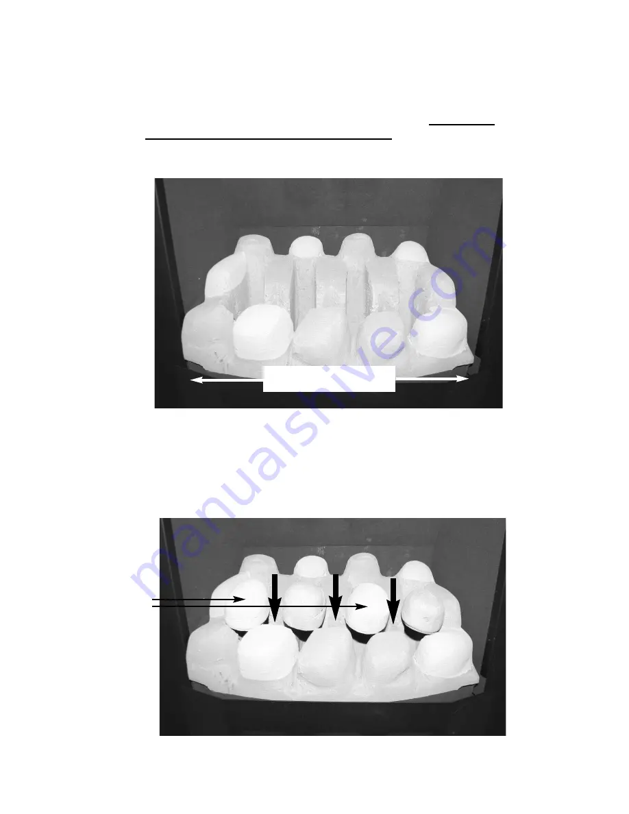
5.9.2
Position the front row of four large loose pebbles along behind the first
row of pebbles, ensuring that the flame paths as indicated are not
interupted. See figure 8 below.
Fig. 8
43
Position fuel-bed base behind
retaining tabs
Beige pebbles
to be
positioned as
indicated


