Flavel Enchant FSCP**MN Installation And Maintenance Instructions Manual Download Page 14

Supplied By www.heating spares.co  Tel. 0161 620 6677

g)

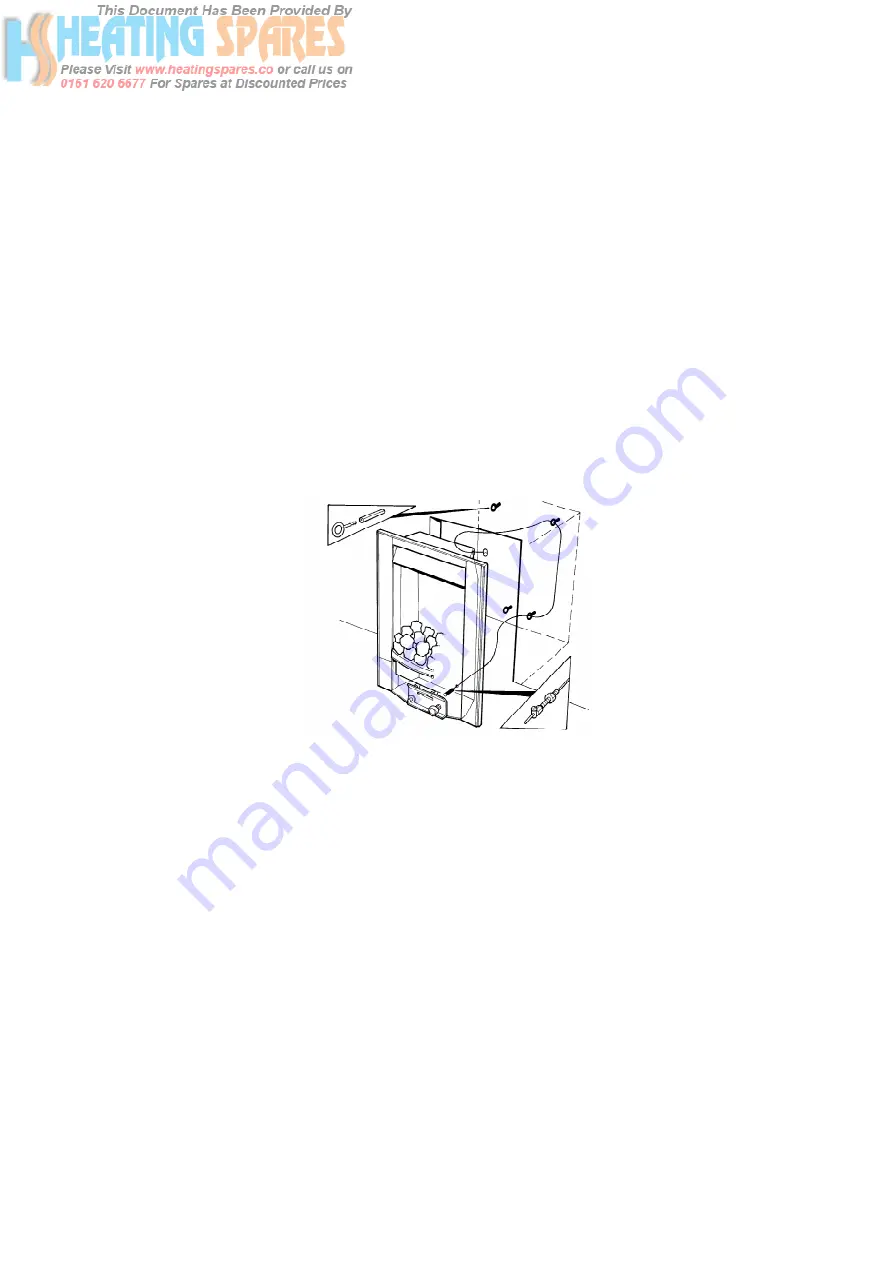
Position the fire carefully on the (protected) surface of the hearth and 
reach into the fire opening.  Thread each of the cables vertically 
downwards through the pair of fixing eyes on the same side of the fire.  
Thread the free end of the cables through the corresponding circular 
hole on each side of the lower rear of the fire.  Carefully slide the fire
box back into the fire opening and pull both cables tight.

h)

Thread a tensioning screw over each of the cables and ensure that the 
tensioning nut is screwed fully up against the hexagon shoulder of the 
tensioning screw (this provides maximum travel for the tensioning nut).

i)

Fit a screwed nipple on to each of the cables and pull hand tight up 
against the tensioning screw, then secure each nipple with a flat 
bladed screwdriver.  See fig. 8 below

Fig. 8

j) 

Evenly tighten the tensioning nuts to tension both cables and pull the 
fire snugly against the wall.  Do not overtighten, it is only necessary to 
pull the seal up against the sealing face of the wall, it does not need to 
be compressed.  Check that there are no gaps behind the seal.

k)

With the fire securely in place, if a concealed gas connection has been 
made through either of the access holes in the sides or rear of the fire, 
the holes should be closed around the pipe to prevent leakage of air 
through the gap around the pipe.

l)

Refit the burner.  Fit the four retaining screws and check that the burner
is correctly locked into position. 

14

Summary of Contents for Enchant FSCP**MN

Page 1: ...0 6677 Enchant PEBBLE FUEL EFFECT GAS FIRE Installation and Maintenance Instructions Hand these instructions to the user Model No s FSCP MN is only for use on Natural Gas G20 at a supply pressure of 2...

Page 2: ...hs 9 1 11 Spillage Monitoring System 9 Section 2 Installation of Fire 2 1 Unpacking the fire 10 2 2 Installing the fire box 10 2 3 Gas soundness and burner pressure 15 16 Section 3 Assembling Fuel Bed...

Page 3: ...preci Single Flame 21100 141 or S I T Dual Flame YA OP 9022 Max Gross Heat Input 6 5 kW Min Gross Heat Input 4 2 kW Cold Pressure 20 0 1 0 mbar Ignition Push button Piezo Electrode Spark Gap 4 5mm Pac...

Page 4: ...s 7 B S 1289 Clay Flue Blocks and Terminals 8 I S 813 1996 Domestic Gas Installation Republic of Ireland No purpose made additional ventilation is normally required for this appli ance when installed...

Page 5: ...f additional overhang over 150mm 1 5 FLUE CHIMNEY INSPECTION Before commencing installation a flue or chimney should be inspected to ensure that all the following conditions are satisfied 1 Check that...

Page 6: ...e test must always be carried out during commissioning of the appliance 1 6 FIRE PLACE OPENING AND CHIMNEY CATCHMENT SPACE The front opening of the fire place must be between 330 and 440 mm wide and b...

Page 7: ...volume fig 2 Opening Width mm Minimum Depth Required mm 330 minimum opening width 222 340 218 350 215 360 211 370 205 380 199 390 193 400 189 410 183 420 178 430 172 440 maximum opening width 168 For...

Page 8: ...pth To increase this depth the fire surround may be packed away from the wall using suitable non combustible board providing the installation is correctly sealed If in doubt about the suitability of t...

Page 9: ...g system in the form of an oxygen sensing pilot This is designed to shut the fire off in the event of a partial or complete blockage of the flue causing a build up of combus tion products in the room...

Page 10: ...nlessTrim 1off each User instruction book and Installation book 2 2 INSTALLING THE FIRE BOX Establish which type of flue you are intending to install the fire in to 225 x 225mm 9 inch x 9 inch brick b...

Page 11: ...that the hearth is protected from damage and carefully lift the fire box into the fire opening then slide it back into position Check that the fire box flange fits flush to the sealing face of the fir...

Page 12: ...nlet elbow The gas connection to the appliance should be made to the isolating inlet elbow using 8mm rigid tubing There must be no soldered joints within the firebox See fig 5 6 below for suggested co...

Page 13: ...f fire opening To fit using the preferred cable method proceed as follows e Mark out and drill 4 off No 14 7mm holes in the back face of the fire opening in the positions shown below in fig 7 Fig 7 Fi...

Page 14: ...travel for the tensioning nut i Fit a screwed nipple on to each of the cables and pull hand tight up against the tensioning screw then secure each nipple with a flat bladed screwdriver See fig 8 below...

Page 15: ...n rear of fire opening the firebox can be secured to the fire surround using four screws and wall plugs provided Below fig 9 is a diagram to indicate the hole centre positions available on the firebox...

Page 16: ...re test point screw for gas soundness with the appliance turned on using a suitable leak detection fluid or detector SECTION 3 ASSEMBLING FUEL BED AND COMMISSIONING 3 1 ASSEMBLING THE FUEL BED a Place...

Page 17: ...ing channel in the front ceramic ensuring they are located onto the lip on the burner front ceramic support See fig 11 below Fig 11 c Select six of the small pebbles and position evenly along the fron...

Page 18: ...flame paths as indicated below are not interupted See fig 13 Fig 13 e Select 2 of the large pebbles and position along the back row of the fuelbed using the location indents on the back section of th...

Page 19: ...tion marked pilot Hold in the control knob for a few seconds to purge the pipe work c Continue to hold in the control knob and press the igniter button If the burner does not light continue to press t...

Page 20: ...utes If the test indicates that spillage is occurring and the flue restrictor baffle has been fitted it should be removed and the test repeated after the fire has cooled d If spillage persists the flu...

Page 21: ...ay and put them in a safe location Remove the loose pebbles from the fuel bed and front ceramic rail Remove the front ceramic from the rail Unscrew the two pozi driv fixing screws which secure the bur...

Page 22: ...ontrol tap locates with a flat in the control panel Carry out a gas soundness test after re assembly 4 4 Removing the Oxy Pilot Assembly Note Because this appliance is fitted with an atmosphere sensin...

Page 23: ...55640 Replacement pebble set B 68970 L H Fibre Board B 56530 R H Fibre Board B 56520 Upper Rear Fibre Board B 56540 Lower Rear Fibre Board B 56550 Piezo Igniter B 1320 Ignition Wire B 14340 Gas Valve...

Page 24: ...Supplied By www heating spares co Tel 0161 620 6677...

Reviews: