™
Computer Numerical Control for Windows
Model 401A
Motor Signal Generator
Hardware Guide
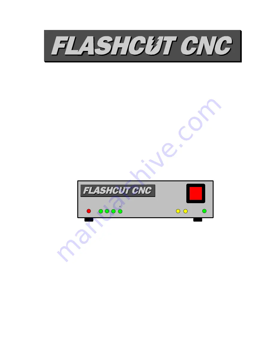
Z
Y
X
A
LIMIT
ON
OFF
RXD TXD
POWER
© 1998 FlashCut CNC, Inc.
1263 El Camino Real, Suite W, Menlo Park, CA 94025
Phone (650) 853-1444
•
Fax (650) 853-1405
•
www.flashcutcnc.com


