background image

............................................................................................................................................................................................... ...............................................................................................................................................................................................

• Do not disconnect any part while unit is in use.

• Do not store a spare propane tank on or near this unit.

• If the heating unit is indoors, detach the propane tank and leave outdoors.

• Always remove protective cover before operating (if applicable).

• Check for leaks after not using the unit for long periods of time.

• Children should never operate this unit. Children must be supervised while near this unit.

• Keep gas tank at least 5 feet away from unit when lit. (if external tank)

• The maximum gas supply pressure is 250psi.

inspected annually and cleaned regularly.

• Inspect all elements of this heating unit before each use. If there is damage, the burner must be 

replaced.

• Be aware of the hazards of high temperatures and stay away from the unit to avoid any burns or 

injury.

of the U.S. Department of Transportation or the National Standard of Canada CAN/CSA-B339, LP gas 

tanks, spheres and tubes for Transportation of Dangrous Goods; and Commission.

•  

revention device and a QCCI or Type I, (CGA791) LP 

gas tank connection.

•  

•   Children and adults should be alerted to the hazards of high surface temperatures and should 

stay away to avoid burns or clothing ignition.

• Young children should be carefully supervised when they are in the area of the appliance.

near the appliance.

• Any guard or other protective device removed for servicing the appliance shall be replaced

prior to operating the appliance.

may be required as necessary. It is imperative that the control compartment, burners and 

circulating airways of the appliance are kept clean. 

Only use the regulator and hose assembly provided with this unit. 

Inspect the burner before use of this unit. If the burner shows any kind of damage, do not operate 

the appliance. 

NOTE: You must follow all steps to properly assemble this heating item. Make sure the gas 

valve is turned “OFF” before assembling. Do NOT attempt to assemble without p

...............................................................................................................................................................

roper tools.

Summary of Contents for NAN-FSDC-01-SL-GG

Page 1: ...EATER Customer Service Email CustomerExperience belnickinc com Phone 866 552 2810 NAN FSDC 02 BR GG NAN FSDC 01 SL GG Online Assembly Instructions http ftp flashfurniture com AssemblyInstructions NAN FSDC 01 SL GG pdf ...

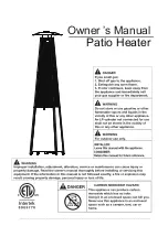
Page 2: ...Owner s Manual Patio Heater ...

Page 3: ...n height 18 in You must use a propane tank that has a collar to protect the gas valve The tank system must be set up for vapor withdrawal Discontinue use if any part of the propane tank is damaged Rust and dents may be hazardous and should be inspected by a gas supplier Do not burn anything other than the provided materials for this patio heater Do not operate unit until all parts are fully assemb...

Page 4: ...nada CAN CSA B339 LP gas tanks spheres and tubes for Transportation of Dangrous Goods and Commission revention device and a QCCI or Type I CGA791 LP gas tank connection Children and adults should be alerted to the hazards of high surface temperatures and should stay away to avoid burns or clothing ignition Young children should be carefully supervised when they are in the area of the appliance nea...

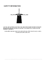
Page 5: ...R ITEMS THAT ARE STORED ABOVE BESIDE OR UNDER THIS HEATER WHILE IN USE WILL BE SUBJECT TO RADIANT HE AT AND COULD BE SERIOUSLY DAMAGED Combustible materials should not be within 48 inches of the top of the unit or within 48 inches around the entire unit ...

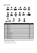
Page 6: ... to assemble the product Estimated Assembly Time 90 minutes Item Description Qty 4 4 4 4 18 3 3 6 4 30 1 1 1 1 1 1 AA BB CC DD EE FF GG HH I I JJ KK LL MM NN OO PP Screw 3 16 Philips screwdriver LL Screw M4 X 8 AA BB DD EE Stud CC M6 nut Wing nut MM Wrench FF GG II Screw M5x10 Bracket HH Flat washer Knob Ground fixer Ground fixer screws KK OO PP JJ Large flat washer NN AA Battery 1 5 V Bolt M6x10 ...

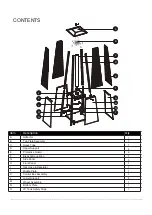
Page 7: ...Tube Protective Guard A B C Top Plate Assembly Upper Support Black Silicone Ring D E Side Panel F G Front Panel H H O Lower Support L Control Box Assembly K Middle Plate J Gas Hose Regulator I O Wheel Assembly Bottom Plate LP Tank Safety Strap M N 1 1 1 4 4 1 3 1 1 1 1 4 1 1 1 ...

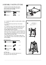
Page 8: ... 3 Insert the pins of the bottom plate N to the holes of lower support L press to secure the pins using 4pcs screw M5x10 to secure the bottom plate and lower support Insert the pins of the control box assemblyy K to the holes of lower support L press to secure the pins using 4pcs screw M5x10 to secure the lower support and control box assy 2 4 Assemble the LP Tank Safety Strap O to lower support L...

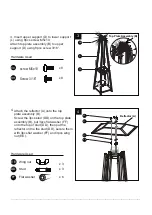
Page 9: ...3 16 Hardware Used Hardware Used 4 4 Attach the reflector A onto the top plate assembly B Screw the 3pcs stud DD on the top plate assembly B put 3pcs flat washer FF onto the top of stud DD then put the reflector on the the stud DD secure them with 3pcs flat washer FF and 3pcs wing nut EE EE FF FF DD x 3 x 3 x 6 EE Wing nut Stud DD FF Flat washer Top Plate Assembly B Reflector A ...

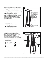
Page 10: ... firmly in the black silicone ring 5 Carefully install the glass tube C by lifting up and inserting through the center hole in the top plate assembly B Ensure the black silicone ring F is attached to the lower edge of the glass tube C as illustrated Slide the glass tube C through the hole of the lower plate cover and onto the middle plate J Check and ensure that the glass tube C is positioned prop...

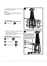
Page 11: ...m plate N Hardware Used x 1 II Knob KK x 1 x 1 Screw M4 X 8 JJ Large flat washer 7 Assemble three side panels G to heater using 18pcs screw 3 16 Attention Do not cover the front side where the control knob is Note Put screw KK through large flat washer JJ then through the end link of the retainer chain Insert screw into hole on front door panel and attach the knob II KK ...

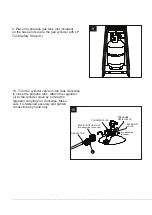
Page 12: ...e tank clockwise CYLINDERVALVE PRESSURE RELIEFVALVE BLEED OFF VALVE turn clockwise to reseal BLACK COUPLING NUT turn clockwise to connect REGULATOR to close the propane tank Attach the regulator J to the cylinder valve by turning the regulator coupling nut clockwise Make sure it is fastened securely and tighten connections by hand only J 9 10 ...

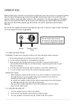
Page 13: ...control knob to the Pilot position and hold for 60 seconds Whilst still holding the control knob down press the ignition button A pilot flame should appear 4 Once the blue pilot flame stays alight constantly let go of the variable knob 5 Turn the variable control knob to the desired temperature position Lo to Hi IMPORTANT NOTE When lighting the heater for the first time or a new LP cylinder is con...

Page 14: ...t cloth Harsh weather conditions may cause stains discoloration and possibly rust pitting Permanent damage may occur if powder or solvent comes in contact with painted or plastic components on this heating unit Keep the heating unit stored away from direct sunlight If storing this unit inside disconnect the propane gas tank from the gas valve Not using manufacturer approved or supplied parts acces...

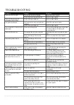
Page 15: ...nutes of operation There is thick black smoke There is blockage in the burner Turn off the heater and let it cool Remove the blockage and clean the inside and outside of the burner The heater produces a whistling noise when the burner is lit Air passageways are blocked Check the minimum installation clearances and air passageways for debris There is air in the gas line Operate the burner until the...

Reviews: