background image

16

VERTICAL WINDLASS MANUAL


VOLUME ONE 

8 Troubleshooting

1.  Anchor falls down independently while windlass is not in use.

• 

This problem is a result of not securing the anchor rode combined with the gypsy drive 

cap being slack. Tighten the gypsy drive cap using the Five Oceans wrench and always 

secure the anchor rode independently of the windlass when not in use.

2.  Failure to operate or sluggish operation.

• 

The majority of these problems are electrical in nature. It is essential that the proper 

voltage be maintained. The proper voltage on a 12 Volt system is 13.5 Volts, constant low 

voltage will damage motor. 

• 

Ensure electrical cable size is large enough to handle the current draw and keep voltage 

drop within acceptable limits (maximum 10%).

• 

Check control switches, connections, battery condition, isolator switch, fuse and motor 

for operation failure.

3.  Failure to operate.

• 

Is there a voltage at the input terminals to the contactor and switches. Check the circuit 

breaker/ isolator switch and any fuses.

• 

Operate the switch. Is there voltage at the positive switch terminal on the solenoid. If 

not, the switch (or its wiring), is difective.

• 

Keep the switch activated. Is there voltage at the main output terminal on the contactor. 

If not check the contactor coil ground circuit. If okay, replace the contactor.

• 

Check the voltage at the motor. If voltage of at least 12.5 volts is present and the motor 

does not operate, the motor is defective.

7.1 Servicing Schedule

The service period is determined by the frequency of use. Professional user will need to carry 

out these operations more often than the weekend user. Before commencing any work on this 

or any other electrical product, isolate from the power source.

Bedding in period:

When new there are some areas that will need frequent checking. If no movement is found 

they can be inspected less often.

• 

Examine all electrical connections, to make sure they are sound and corrosion hasn’t set 

in. Tighten if necessary and protect if required.

• 

Check mounting studs are firmly clamped and tighten if required.

After use:

• 

Wash down the windlass using fresh water.

• 

Ensure rode is at least 12” (300mm) below the windlass

• 

Check anchor locker drain

• 

Check rode and splice for wear.

Annually or more often if frequent user:

• 

Examine all electrical connections, to make sure they are sound and corrosion hasn’t set 

in. Tighten if necessary and protect if required.

• 

Check mounting studs are firmly clamped and tighten if required.

• 

Check rode and splice for wear.

• 

Check gypsy as it is a high wear item

7- Servicing 

WARNING! Isolate the windlass 

using circuit breaker/isolator

WARNING! Ensure rode is adequately 

secured to an independent strong point

Summary of Contents for ATLANTIC WINDLASS 600

Page 1: ...PACIFIC WINDLASS SERIES O W N E R M A N U A L 6 0 0 9 0 0 1 0 0 0 1 5 0 0 M O T O R S SAVE THESE INSTRUCTIONS Important safety instructions are included in this manual ...

Page 2: ...es Fitting the Windlass to the Deck Electrical Wiring Electric Cable Selection Wiring Control Switch Installation Wiring Diagram Operation Manual Control Power Down Up Windlass Operating Procedures Servicing Servicing Schedule Troubleshooting Warranty Product Guide 3 3 6 7 7 7 7 8 8 10 10 10 10 11 13 13 13 14 16 16 16 17 19 ...

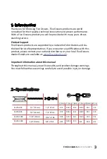
Page 3: ...h this product please contact your national distributor or your local Five Oceans dealer Details are available at www five oceans com Important information about this manual Throughout this manual you will see safety and product damage warnings You must follow these warnings carefully to avoid possible injury or damage Pacific 600 2 Specifications 1 2 12mm 1 2 12mm 8 73 8 73 D mm D in P in W in P ...

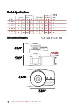
Page 4: ...ns Diagram 12 12 12 12 Pacific 900 Pacific 1000 Pacific 1500 MODEL MOTOR Voltage Watt 600 900 1000 1500 450 657 750 1200 990 1450 1650 2640 kg lb MAXIMUM PULL 26 40 40 40 m min ft min DROP SPEED 85 131 131 131 150 220 250 485 330 484 550 1067 kg lb WORKING LOAD LIMIT 33 55 60 95 Amp NORMAL CURRENT DRAW MAX ...

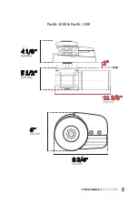
Page 5: ...5 FIVE OCEANS PACIFIC SERIES Pacific 1000 Pacific 1500 MAX ...

Page 6: ...al for danger serious injury or death Five Oceans windlasses are designed and supplied for anchor control in marine applica tions and are not to be used in conjunction with any other use Keep limbs fingers clothing and hair clear of windlass and anchor rope chain and anchor during operation Severe bodily harm would result Ensure there are no swimmers or divers nearby when dropping anchor When the ...

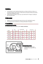
Page 7: ... switched off the power before you start installing this product This product requires installation by a suitably qualified electrical engineer 4 Installation 4 1 Basic requirements Each installation requires the following tools Windlass Installation WIRING INSTALLATION Crimping Pliers Wire Stripper Suitable electrical cable and crimp terminals Pacific 600 5 16 5 16 5 16 5 16 Pacific 900 Pacific 1...

Page 8: ...scale of the template matches the winch 12 300 mm 4 3 2 4 3 3 4 2 Accessories Use only genuine Five Oceans parts and accessories to ensure top performance and eliminate the risk of voiding your warranty For replacement parts please visit your dealer or www five oceans com 4 3 Fitting The Windlass to the Deck 1 If the deck is not flat a suitable mounting pad may be required to take up camber or she...

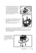
Page 9: ... the studs into the base finger tight with the flats towards the base as shown Fig 4 3 5 6 Next tighten the studs until they bottom out in their holes Do this to each of the studs in turn Pass all the studs through the deck and fit them security on the motor piece which is on the underside of the deck and secure the unit with the fixings provided 7 Place the base mat in position on the deck option...

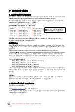
Page 10: ...rip to the off position Warning If you are not sure you understand these guidelines seek professional help Ensure that the installation complies with USCG ABYC NMMA or other local regulations 5 3 Control switch installation The unit is supplied with Visit www five oceans com for more information Contactor box should be located within an dry area and control box used in some installation refer to w...

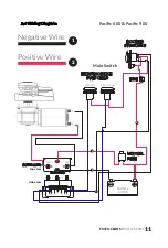
Page 11: ...IES 5 4 Wiring Diagram Positive Wire Negative Wire MOTOR FUSE FUSE ELECTRIC DECK Main Switch SWITCHES ROCKER SWITCHES SOLENOID top view Foot Up Foot Down side view A2 A1 M1 M2 C Battery 12 VDC 2 2 2 1 1 1 Pacific 600 Pacific 900 ...

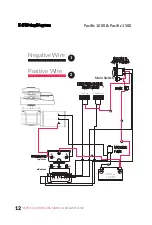
Page 12: ...E ONE Positive Wire Negative Wire MOTOR FUSE FUSE ELECTRIC DECK Main Switch SWITCHES ROCKER SWITCHES SOLENOID top view Foot Up Foot Down side view A2 A1 M1 M2 C Battery 12 VDC 2 2 2 1 1 2 2 Pacific 1000 Pacific 1500 5 4 Wiring Diagram ...

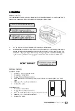
Page 13: ...clockwise and engage the anchor locks Remove the wrench handle To release anchor 1 Check unit is not in manual mode 2 Release any anchor locks 3 Engage the circuit breaker isolator 4 Press down button continuously until you ve reached the necessary length of chain rope 5 Disengage the circuit breaker isolator 6 Lock anchor locks To retrive anchor 1 Release any anchor locks 2 Engage the circuit bre...

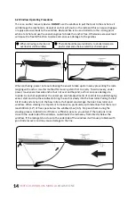
Page 14: ... approaches the vessel use careful adjustments of controls to avoid damaging vessel start and stop the windlass to bring the anchor slowly into the bow roller Pulling the last bit of rode and anchor into the bow roller at full speed can damage the boat bow roller and windlass When stowing it is important to make sure particularly with rode lines that there is at least 300mm 12 of free space below ...

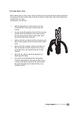
Page 15: ...ds back into the line Because of wide variations in rope type and construction some experimentation may be required Whip the line with permanent whipping at the beginning of the taper The method of joining illustrated is designed to minimize chafe between the rope and chain but as a matter of prudent seamanship the splice should be checked regularly and remade if there is any evidence of wear 6 3 ...

Page 16: ...eck the contactor coil ground circuit If okay replace the contactor Check the voltage at the motor If voltage of at least 12 5 volts is present and the motor does not operate the motor is defective 7 1 Servicing Schedule The service period is determined by the frequency of use Professional user will need to carry out these operations more often than the weekend user Before commencing any work on t...

Page 17: ...ective in materials or workmanship d Responsibility for the selection of products appropriate for the use intended by the Buyer shall rest solely with the Buyer e This warranty does not cover any incidental costs incurred for the investigation removal carriage transport or installation of the product f A unit provided as an exchange or replacement parts will be subject to the warranty of the origi...

Page 18: ... obligation to cover any loss of time use of this product freight or any incidental or consequential claim by anyone from using this product b THIS WARRANTY IS IN LIEU OF ALL OTHER WARRANTIES EXPRESS OR IMPLIED INCLUDING WARRANTIES OF MERCHANTABILITY OR FITNESS FOR A PARTICULAR PURPOSE c Baron USA LLC or any of the product resellers will not be liable for death injuries to persons or property or f...

Page 19: ...here Circuit Breaker 60 Amp Product Number 3295 For more info click here Circuit Breaker 80 Amp Product Number 3294 For more info click here Dual Direction Solenoid Product Number 3292 For more info click here Foot Switch Product Number 3291 For more info click here Not Included in Package examples Stainless Steel Chain Stopper Product Number 75 For more info click here Stainless Steel Chain Stopp...

Page 20: ...www five oceans com VOLUME ONE Copyright 2019 Baron USA LLC All rights reserved ...

Reviews: