background image

13

COMPUTER OPERATION GUIDE

5. USER DEFINED PROGRAMME

There are 3 programs U1, U2, U3 for user defined.

7.1. Setting

Press program key to select any U1-U3 for self setting program.Then press MODE key enter 

to self condition, the speed& incline window show the value of the segment. By plus or minus 

to adjust the speed and incline paragraph. Press the MODE button to confirm and at the same 

time setting the next period. After finishing the 20th time setting. You can storage all data till 

next time you get a new setting, This data won’t lost by outage.

7.2. Start

A: Under standby mode, press “PROG” continuous to set user defined program(U01-U03) 

directly. When time setting is ready, press “START” to start.

B: After setting user program and time, press START to start running.

7.3. Setting manual

Each program divide into 20 time segments equally. Only finish the setting each time segment 

for speed and incline, you can start the treadmill

5. HEART BEAT TEST

When holding the hand pulse by two hands, the pulse window will show your heart beat after 5 

seconds. In order to get an accurate heartbeat value, please holding the hand pulse more than 

30 seconds to test when the machine stop. The heart beat data is just for reference, can not be 

as the medical data.

6. BODY FAT TEST

When the treadmill standby, press ‘ PROGRAM’ button till ‘ FAT’ show in the window. ‘FAT’ is 

body fat test mode. Press ‘ MODE’ to choose parameter ‘ SEX / AGE / HEIGHT / WEIGHT’, 

Corresponding window will show “-1-”,“-2-”,“-3-”,“-4-”. When set each parameter, press  

SPEED+/- to adjust the data, and Corresponding window will show the data and press ‘MODE’ 

button to finish, the window will show“-5-” and“---” enter into ready to go condition. Hold the 

handle pulse with two hands, it will show your BMI data after 5 seconds.

Parameter Type Default

Setting range

Mark

SEX (F1)

1 (MALE)

1—2

1= MALE 2= 

FEMALE

AGE (F2)

25

10—99

HEIGHT (F3)

170 CM

100—240 CM

WEIGHT (F4)

70KG

20—160KG

Summary of Contents for F4H-TM-D2450

Page 1: ...ain important information which will help you get the best from your equipment and ensure safe and correct assembly use and maintenance If you need help or have damaged or missing parts call the Custo...

Page 2: ...p 3 Step 4 Step 5 Step 6 Folding Instructions Technical Parameter Computer Operation Guide Exercise Instructions Warm Up Running Belt Adjustment Exploded Drawing Parts List Troubleshooting Declaration...

Page 3: ...or adults Juveniles need be accompanied with adults while workout 9 You must hold on to the handrails until you become comfortable and familiar with the treadmill when first start the workout 10 Tread...

Page 4: ...ot get through power before complete assembly IMPORTANT SAFETY INFORMATION NO DES Specification Qty NO DES Specification Qty 1 Main frame 1 12 5 Allen wrench 5mm 1 70 Bolt M8 45 2 Bolt M8 16 4 4 83 Le...

Page 5: ...ss the computer wire when folding the computer 1 Put the computer as below illustration screw off Bolt M8 16 51 and the Lock washer 64 of Left Upright and Right Upright 2 Lock the Computer frame to Le...

Page 6: ...in upright keep touch the upright and computer by hand that they will not fall down escaping any hurt STEP 4 1 Use the 5 Allen wrench lock the Bolt M8 45 70 and Lock washer 64 lock the Right Upright...

Page 7: ...upright and base Left side assembly method same as right side STEP 6 Put the safety key 71 on the computer ATTENTION Please confirm complete assembly as the require above and lock all the bolt Do the...

Page 8: ...till hearing the sound that the air pressure bar B is locked into the round tube PULLING DOWN 1 Support place A with hand kick the place of air pressure bar then the base frame will fall down automati...

Page 9: ...is properly installed and grounded in accordance with all local appliance DANGER Improper connection of the equipment grounding conductor can result in a risk of electric shock Check with a qualified...

Page 10: ...unt down mode distance count down mode calories count down START button Press this button to start the machine the machine will run at the lowest speed or at the speed of default program after 3 secon...

Page 11: ...he time setting arrange 5 00 99 00 Press MODE to get into the distance count down mode DISTANCE window display 1 00 press button SPEED SPEED INCLINE INCLINE could set running distance setting arrange...

Page 12: ...3 4 5 3 4 5 3 3 3 6 6 5 3 3 INCLINE 4 4 4 4 3 3 6 6 6 7 7 8 8 9 9 6 6 5 4 4 P08 SPEED 2 3 3 6 7 7 4 6 7 4 6 7 4 4 4 2 3 4 4 2 INCLINE 4 5 5 5 6 6 6 7 8 9 9 9 10 10 10 12 12 8 6 3 P09 SPEED 2 4 4 7 7 4...

Page 13: ...finish the setting each time segment for speed and incline you can start the treadmill 5 HEART BEAT TEST When holding the hand pulse by two hands the pulse window will show your heart beat after 5 se...

Page 14: ...ll stop emergency If the safety key is not on it s position any button is Invalid 9 POWER SAVE MODE Stopped for more than 10 minutes without any operation the system completed all showed off into the...

Page 15: ...you about 12 minutes in 1 km If you feel comfortable at the stable velocity you can add the speed and incline after 30 minutes you can have good exercise At this stage you can not add the speed or inc...

Page 16: ...ent the intensity of exercise Please stop at once If you feel chest tightness chest pain irregular heart beat breath difficulty dizziness or other discomfort during exercise You should consult with yo...

Page 17: ...straight hand try to touch the toes Maintain 10 to 15 seconds then relax Repeat for each leg do three times see Figure 2 3 Legs and feet tendon stretch two on the Rotary wall or tree stand one foot in...

Page 18: ...nction and life of your treadmill thus requiring periodic lubrication We recommend a periodic inspection of the deck You need contact with our service center if you find the damage of the deck We reco...

Page 19: ...clock and switch turn the right adjusting bolt 1 4 turn clockwise then start running until centering the belt PIC B If the belt has drifted to the left pull out of the safety clock and switch turn th...

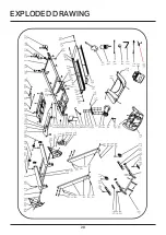
Page 20: ...20 EXPLODED DRAWING...

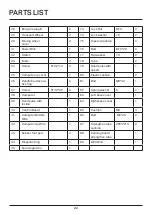
Page 21: ...r 1 56 Bolt ST4 2 12 5 12 5 Allen Wrench 5mm 1 57 Bolt M5 8 5 13 Bolt M10 42 1 58 Lock Nut M8 8 14 DC Motor 1 59 Bolt M8 25 1 15 Running Board 1 60 Screw ST4 2 19 8 16 Incline motor 1 61 wrench w scre...

Page 22: ...er up cover 1 80 Elastic cushion 2 36 Handle bar decora tive ring 2 81 Bolt M8 42 1 37 Screw ST4 2 20 6 82 Spring washer 5 2 38 Computer 1 83 Left base cover 1 39 Hand pulse with incline 1 84 Right ba...

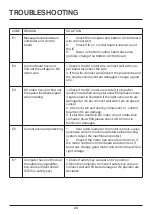
Page 23: ...se check if light sensor is fixed well if the light sensor wire are damaged or it s pin connect well with 4 pin on speed sensor 2 Check if 4 pin and nearby component or control board and IC are damage...

Page 24: ...directive EN 60335 1 2012 A11 2014 A13 2017 EN62233 2008 Directive 2014 35 EU EMC compliance has been granted that the samples of the product have been tested and found to be in conformity with test...

Page 25: ...25...

Reviews: