Instruction Manual
D103211X012
NotchFlo DST Valve
March 2011
22
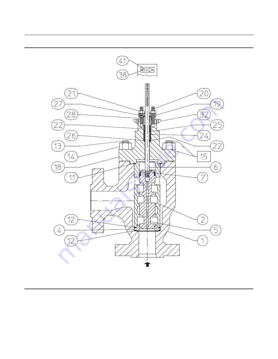
Figure 11. Fisher NotchFlo DST CL1500 Cast Angle Valve Assembly (NPS 1 through 8)
GG08666-A
j
APPLY LUB
CL1500 NPS 4, 4-STAGE
NotchFlo DST SHOWN
FLOW
FLOW UP
Page 1: ...property damage it is important to carefully read understand and follow all the contents of this manual including all safety cautions and warnings If you have any questions about these instructions c...
Page 2: ...s in this manual and any applicable standard or code limitation for valve should not be exceeded Figure 2 Fisher NotchFlo DST Trim W8538 1 NotchFlo DST control valves utilize a high resistance multi s...
Page 3: ...be Valves 2 CL900 and CL1500 95 85 210 185 3 185 140 405 310 4 340 280 750 620 3 Stage Angle Valves 1 CL600 20 44 2 42 93 3 86 190 4 140 315 6 300 660 8 605 1340 4 Stage Angle Valves 1 CL900 and CL150...
Page 4: ...y do not use this tapped hole to lift the valve assembly or personal injury may result from the assembly falling CAUTION When ordered the valve configuration and construction materials were selected t...
Page 5: ...ure or uncontrolled process fluid Before starting disassembly D Do not remove the actuator from the valve while the valve is still pressurized D Always wear protective gloves clothing and eyewear when...
Page 6: ...R 1 Figure 4 Detail of Graphite Ribbon Filament Packing for Plain and Extension Bonnets PACKING FOLLOWER KEY 28 LANTERN RING KEY 24 PACKING BOX RING KEY 26 1 12 7 mm 1 2 INCH STEM SINGLE ARRANGEMENTS...
Page 7: ...graphite ULF packing unless otherwise indicated WARNING To avoid personal injury or equipment damage resulting from packing leakage inspect the valve plug stem and packing box wall for nicks or scrat...
Page 8: ...481 827 908 60 85 175 250 310 355 610 670 3 20 3 25 4 80 4 88 6 38 6 45 6 38 6 45 0 126 0 128 0 189 0 192 0 251 0 254 0 251 0 254 If there is undesirable packing leakage with other than spring loaded...
Page 9: ...t would prevent the packing from sealing 4 Remove the stem connector and slip the packing rings over the end of the valve plug stem 5 Reassemble the packing follower upper wiper packing flange and pac...
Page 10: ...alve body fluid pressure has been relieved 5 Hex nuts key 14 attach the bonnet to the valve body Loosen these nuts approximately 3 mm 1 8 inch Then loosen the body to bonnet gasketed joint by either r...
Page 11: ...Figure 6 Installing Graphite Ribbon Filament Packing Rings One at a Time VALVE STEM PACKING FOLLOWER BONNET TOP OF PACKING RING EVEN WITH BOTTOM OF ENTRANCE CHAMFER INSTALLING SECOND PACKING RING A22...
Page 12: ...m recommended torque shown in table 3 or 4 Then loosen the packing flange nuts and retighten them to the recommended minimum torque shown in table 3 or 4 For other packing types tighten the packing fl...
Page 13: ...ugh 12 except where indicated With metal seat constructions lapping seating surfaces of the valve plug and seat ring keys 5 and 4 can improve shutoff Deep nicks should be machined out rather than grou...
Page 14: ...that run across the serrations are not permitted under any conditions since they will prevent the gaskets from sealing properly 1 Install the seat ring gasket key 12 into the valve body Install the se...
Page 15: ...packing box parts per steps 15 and 16 of the Replacing Packing procedure Be certain to observe the note given prior to step 15 of that procedure 10 Mount the actuator by following the procedures in th...
Page 16: ...t numbers not shown contact your Emerson Process Management sales office Key Description Part Number 1 Valve Body If you need a valve body as a replacement part order by valve size serial number and d...
Page 17: ...Instruction Manual D103211X012 NotchFlo DST Valve March 2011 17 Figure 7 Fisher NotchFlo DST CL600 Balanced Globe Valve Assembly NPS 1 through 8 GE14589 j APPLY LUB 5 INCH YOKE BOSS VIEW A FLOW A...
Page 18: ...tion Manual D103211X012 NotchFlo DST Valve March 2011 18 Figure 8 Fisher NotchFlo DST CL900 and 1500 Balanced Globe Valve Assembly NPS 2 through 4 GE14166 A j APPLY LUB 5 INCH YOKE BOSS VIEW A FLOW FL...
Page 19: ...ve March 2011 19 Figure 9 Fisher NotchFlo DST CL900 and 1500 Unbalanced Angle Valve Assembly NPS 1 to 1 1 2 GE14052 A j APPLY LUB NOTE NotchFlo FORGED BLOCK ANGLE VALVE BODIES UTILIZE DRILLED AND TAPP...
Page 20: ...Balanced Angle Valve Assembly NPS 2 through 4 and CL600 Balanced Angle Valve Assembly NPS 1 through 8 GE14174 A j APPLY LUB NOTE NotchFlo FORGED BLOCK ANGLE VALVE BODIES UTILIZE DRILLED AND TAPPED LI...
Page 21: ...32 16 CL300 3 4 10 UNC 2B 1 13 16 6 CL600 1 8 UN 2B 1 5 24 CL300 3 4 10 UNC 2B 1 23 24 8 CL600 1 1 8 8 UN 2B 1 69 24 CL300 7 8 9 UNC 2B 1 31 24 1 CL900 1500 7 8 9 UNC 2B 1 31 8 1 1 2 1 8 UNC 2B 1 5 8...
Page 22: ...on Manual D103211X012 NotchFlo DST Valve March 2011 22 Figure 11 Fisher NotchFlo DST CL1500 Cast Angle Valve Assembly NPS 1 through 8 GG08666 A j APPLY LUB CL1500 NPS 4 4 STAGE NotchFlo DST SHOWN FLOW...
Page 23: ...2 Fisher NotchFlo DST CL1500 w NPS 6 and CL2500 Balanced Angle Valve Assembly NOTE NotchFlo FORGED BLOCK ANGLE VALVE BODIES UTILIZE DRILLED AND TAPPED LINE FLANGE BOLTING CONNECTIONS CL1500 NPS 6 4 ST...
Page 24: ...are available upon request We reserve the right to modify or improve the designs or specifications of such products at any time without notice Neither Emerson Emerson Process Management nor any of th...