


Instruction Manual
D104296X012
LCP200 Local Control Panel
August 2018
4
Specifications (continued)
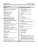
Pushbuttons
Protected with lockable covers
Top (Reset):
After an emergency demand—
commands the valve to its normal position only after
loop current is restored (manual reset)
Middle (Trip):
Commands the valve to the configured
trip position
Bottom (Test):
Commands the configured partial
stroke test. Can be overridden by the Trip button,
Reset button, or Emergency Demand
1. The pressure/temperature limits in this document and any other applicable code or standard should not be exceeded.
2.
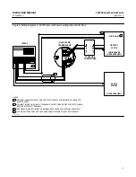
DVC6000 SIS: Cable length is limited by maximum cable capacitance of 240,000 pF, typically 765 meters (2510 feet).
3. DVC6200 SIS FW7 or later required for Auto detection of power source.
4. DVC6200 SIS FW7 or later is required for the test contact to change state.
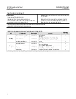
Table 2. Electromagnetic Immunity Performance for Fisher LCP200
Port
Phenomenon
Basic Standard
Test Level
Performance
Criteria
Enclosure
Electrostatic discharge (ESD)
IEC 61000-4-2
$
4 kV contact
$
8 kV air
A
Radiated EM field
IEC 61000-4-3
80 to 1000 MHz @ 10V/m with 1 kHz AM at 80%
1400 to 2000 MHz @ 3V/m with 1 kHz AM at 80%
2000 to 2700 MHz @ 1V/m with 1 kHz AM at 80%
A
Radiated Power Magnetic
IEC 61000-4-8
30 A/m
A
I/O signal/
control/power
Burst (fast transients)
IEC 61000-4-4
$
1 kV, I/O lines
$
2 kV, DC power lines
A
Surge
IEC 61000-4-5
$
1 kV, I/O lines (line-to-ground)
$
2 kV, DC power line (line-to-ground)
$
1 kV, DC power line (line-to-line)
B
Conducted RF
IEC 61000-4-6
150 kHz to 80 MHz at 3 Vrms with 1 kHz AM at 80%
A
1. A = No degradation during testing. B = Temporary degradation during testing, but is self-recovering.