


Design RSS
5
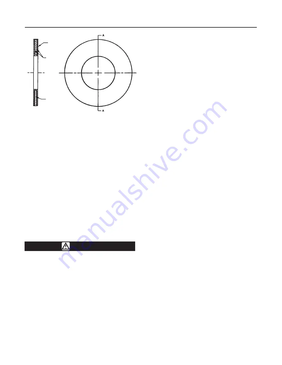
Figure 4. Typical Line Flange Gasket (Key 18)
PTFE
COMPOSITION
STAINLESS STEEL
10B3224–C
A5039 / IL
7. If the actuator and valve are shipped separately,
refer to the appropriate actuator instruction manual for
the actuator mounting procedure.
Maintenance
Valve parts are subject to normal wear and must be
inspected and replaced as necessary. Inspection and
maintenance frequency depends on the severity of
service conditions. This section includes instructions
for packing and trim replacement. All these mainte-
nance operations may be performed with the valve in
the line.
Due to the care Fisher Controls takes in meeting all
manufacturing requirements (heat treating, dimension-
al tolerances, etc.), use only replacement parts sup-
plied by Fisher Controls.
WARNING
Avoid personal injury or property dam-
age from sudden release of process
pressure or bursting of parts. Before
performing any maintenance opera-
tions:
D
Disconnect any operating lines pro-
viding air pressure, electric power, or a
control signal to the actuator. Be sure
the actuator cannot suddenly open or
close the valve.
D
Use bypass valves or completely
shut off the process to isolate the valve
from process pressure. Relieve process
pressure from both sides of the valve.
Drain the process media from both
sides of the valve.
D
Vent the power actuator loading
pressure and relieve any actuator spring
precompression.
D
Use lock-out procedures to be sure
that the above measures stay in effect
while you work on the equipment.
Note
Whenever a line flange gasket (figure 4)
seal is disturbed by removing the valve
from the line, install a new gasket on
reassembly. This is necessary to ensure
a good gasket seal.
Packing Maintenance
Key numbers are shown in figure 9.
The packing consists of braided packing rings (key
13). The packing box is only a safety measure in case
of a leak through the bellows (key 6). Therefore, the
packing follower (key 11) is tightened to 10 lbf
S
in (1.13
N
S
m) of torque and then loosened one half turn. To
detect a leak through the bellows (key 6), the bonnet
(key 2) can be provided with a connection for leak-off
piping.
Replacing Packing and Bushing Inserts
Key numbers are shown in figure 9.
1. Isolate the control valve from the line pressure. Re-
lease pressure from both sides of the valve and drain
the process media from both sides of the valve.
2. Exhaust all actuator pressure, and disconnect the
operating lines from the actuator and any leak-off pip-
ing from the bonnet (key 2). Disconnect the actuator
stem connector, and then remove the actuator from
the valve by unscrewing the yoke locknut (key 14).
3. Remove any travel indicator parts, the locknut (key
10), and the travel stop (key 16) from the valve stem
(key 5) threads.
4. Remove the packing follower (key 11). Unscrew
the cap screws (key 7) and hex nuts (key 8) that se-
cure the bonnet (key 2) to the valve (key 1). Then,
carefully lift the bonnet off and set it on a protective
surface to prevent damage to the bonnet sealing sur-
face. If the valve stem, bellows, and valve plug (keys
5, 6, and 3) come out with the bonnet, remove these
parts from the bonnet. For metal bellows, remove the
gasket (key 27). For 1/2- and 3/4-inch sizes, remove
the O-ring (key 30) from the bonnet.