


4194A, B, and C Series
2–1
Section 2
Installation
Controller Mounting Orientation
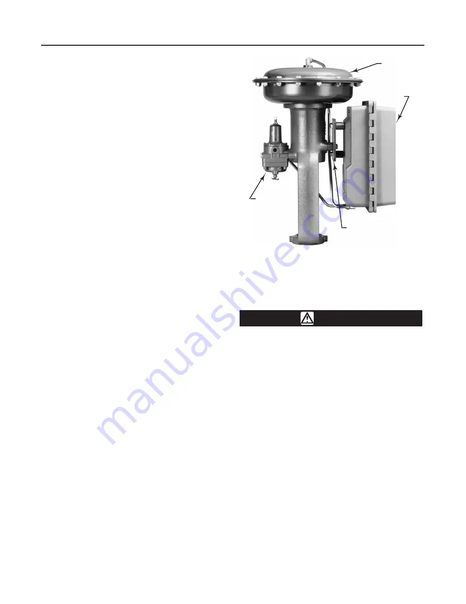
Mount the controller with the housing vertical, as
shown in figure 2-1, so that the vent points down.
Pipestand Mounting
Refer to figure 2-2. Pipestand mounting parts are pro-
vided to mount the controller to a 2-inch (nominal)
pipe. Attach a bracket (key 68) to the controller with
cap screws (key 66) and lock washers (key 67). Attach
two clamps (key 69) to the bracket, and fasten the
controller to the pipe.
Panel Mounting
Using the dimensions shown in figure 2-3, cut a hole in
the panel surface. Slide the controller into the hole and
attach the bracket (key 68) to the rear of the controller
using three cap screws (key 66) and lock washers
(key 67). Tighten the screws (key 70) to seat the case
snugly and evenly against the panel surface.
Wall Mounting
Using the dimensions in figure 2-4, drill holes in the
wall to align with the four holes in the bracket (key 68).
If the tubing is to run through the wall, drill a hole in
the wall large enough to accept the tubing.
Mount the controller to the bracket using three cap
screws (key 66) and lock washers (key 67). Attach the
bracket to the wall, using suitable screws or bolts.
Actuator Mounting
Refer to figure 2-1. A controller specified for mounting
on a control valve actuator is mounted at the factory. If
the controller is ordered separately for installation on a
control valve actuator, mount the unit as described in
this section. Mounting parts vary for different actuator
types.
Attach the mounting bracket to the actuator yoke with
cap screws, lock washers, and spacer spools. Attach
the controller to the bracket with cap screws, lock
washers, and spacer spools. On some designs, the
mounting bracket is attached to the actuator casing
rather than to the yoke.
Figure 2-1. Typical Actuator Mounting
MOUNTING
PLATE
TYPE 657
ACTUATOR
TYPE 4194
CONTROLLER
TYPE 67FR
FILTER
REGULATOR
W5661 / IL
Pressure Connections
WARNING
To avoid personal injury or property
damage resulting from the sudden re-
lease of pressure, do not install any sys-
tem component where service condi-
tions could exceed the limits given in
this manual. Use pressure-relieving de-
vices as required by government or ac-
cepted industry codes and good engi-
neering practices.
Refer to figure 2-5 for piping connection locations.
Supply, output, remote set point, and vent connections
are 1/4-inch NPT, female. Process pressure connec-
tions are 1/4- or 1/2-inch NPT (optional).
Process Pressure Connections
Process pressures are piped to the connections
marked A and B on the bottom of the case, shown in
figure 2-5. Pipe the high pressure line to connection B
and the low pressure line to connection A.
When installing process piping, follow accepted prac-
tices to ensure accurate transmission of the process
pressure to the controller. Install a three-valve bypass,
shutoff valves, vents, drains, or seal systems as need-
ed in the process pressure lines. If necessary, install a


