open
5
/
16
(8mm)
gap between
panels
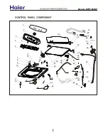
BEFORE YOU START
FOR INTEGRATED DOUBLE MODELS DD603I
(NOTE: FOR SINGLE
R
MODELS, REFER TO BACK OF THIS BOOK)
D O U B L E
R
I N T E G R A T E D P A N E L P R E P A R A T I O N
part number
526608 J
06/2004
(page 1 of 6)
US
WIDTH OF ALL PANELS
Measure
the width between adjacent door/drawer fronts and write it
in the first box below, then complete the equation. For example:
2x
door clearance
(
3
/
32
” (2.5mm) MIN)
HEIGHT OF UPPER PANEL
For example:
15
5
/
8
” (398mm)
0mm
15
5
/
8
” (398mm)
15
5
/
8
(398mm)
door extension
(0” recommended)
height of upper panel
standard height
HEIGHT OF LOWER PANEL
Measure
door/drawer height (or equivalent) and write it in the first
box below, then complete the equation. For example:
height of lower panel
(12
17
/
64
” (311.5mm) MIN)
MIN 28
1
/
4
” (717.5mm) +
height of upper panel
Note: The ‘Door Extension’
allows for the top of the Upper Panel
to be above the
R
where required.
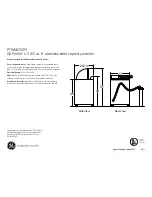
Important!
The air vent between the Upper and Lower Panels must not be
covered. An air gap of
5
/
16
”
(
8mm) MUST be provided.
PLEASE NOTE: Your model of
R
may differ from the model shown in the diagrams. Diagrams have been simplified to enable clearer instruction.
FOLLOW THESE INSTRUCTIONS BEFORE REFERRING TO PRODUCT INSTALLATION INSTRUCTION SHEET P/N 526607.
The Door and Toe Kick Panels
of the
R
can be
made to match your kitchen
cabinetry. This diagram,
with the addition of your own
measurements will help you
calculate the required panel
sizes.
CABINETRY ALIGNMENT
The following calculations
assume:
The top of the Upper Panel is
to be aligned with the top of
the adjacent cabinetry. The
final panel/cabinetry alignment
is achieved by adjusting the
R
’s feet
door clearance
standard height
door extension
width of all panels
width of all panels
(23
7
/
16
” (595mm) MIN)
height of upper panel
height of upper panel
air gap
height of lower panel
24
1
/
4
” (616mm)
2 x
3
/
32
” (2.5mm)
24
1
/
16
” (611mm)
30” (762mm)
15
5
/
8
” (398mm)
14
1
/
16
” (356mm)
5
/
16
” (8mm)