Fisher & Paykel DD601Iv2 Service Manual Download Page 21

- 18 -

4.4 

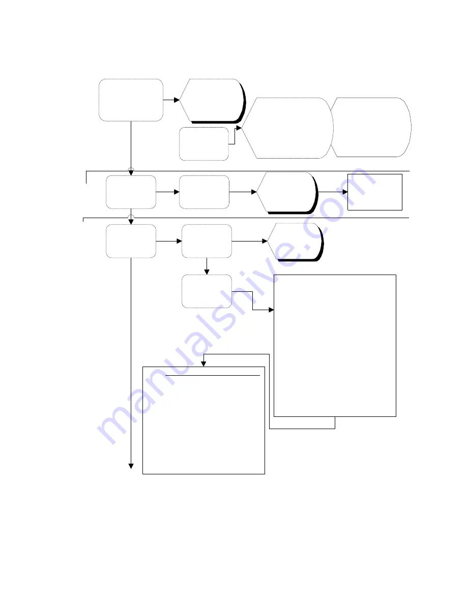
Diagnostics Quick Reference Flow Chart

To clear the current 
fault code press the 

Keylock once. Note if 

you press Keylock 

again you will remove 

the previous fault.

Press and hold 

Keylock, then 

Start/Pause buttons 

for 6 seconds

Press 

Start/Pause 

button

Press Power  

button

Press 

Start/Pause 

button

Press Power 

Button

Press 

Start/Pause 

button

Press Keylock 

button to turn 

output On/Off

All LED's & 

LCD segments 
except Keylock 

are illuminated

Initiate Pen upload via 

Rinse program LED. 

At the same time, first 

the current, then the 

previous fault code will 

be displayed in the 

LCD

Cycles 

through every 

LED & LCD 

segment

Hardware 

output 

diagnostic 

test mode

Disconnect 

power supply to 

exit Show Off 

mode

EU = Exhaust valve 
FU = Water Inlet Valve 
dd = Detergent diverter valve 
Er = Element relay 
LS = Lid seal pump 
rd = Rinse aid dispenser 
P1 = Wash pump motor 
P2 = Drain pump motor  
dF = Drying fan 
temp = currentwater temperature 

Note:

 Display green = output on 

          Display red     = output off 
Tub microswitch can be tested at 
any time. Rinse LED on = Open 
                Rinse LED off =Closed

LED    Heavy   Normal  Light  Delicate       
EU       Off          Off       Off      On 
FU       Off          Off       On      Off 
dd        Off          Off       On      On 
LS        Off          On       Off       Off 
rd         Off          On       Off       On 
P1        Off          On       On       Off 
P2        Off          On       On       On 
dF        On          Off       Off       Off 
Er        On          Off       Off       On 
temp    On          Off       On       Off

#1 Display 
Mode

#2 Show Off/Demo Mode

#3 Hardwre Output Test 
Mode


See Next 

Page

Summary of Contents for DD601Iv2

Page 1: ...DishDrawer Models DD601v2 DD601Iv2 DS601v2 DS601Iv2 599039...

Page 2: ...5 3 4 Filling 6 3 5 Dispensing Detergent 7 3 6 Lid Seal 7 3 7 Wash Cycle 8 3 8 Heating 8 3 9 Filter Plate 9 3 10 Drain Cycle 9 3 11 Drying Cycle 10 3 12 Deflating 10 3 13 Lockring Nut 10 3 14 Wiring C...

Page 3: ...late Removal 36 6 10 Rotor Assembly Removal 36 6 11 Tub Removal 37 6 12 Locking Ring Element Plate Motor Assembly Removal 37 6 13 Lid Assembly Removal 38 6 14 Lid Seal Replacement 38 6 15 Slide Runner...

Page 4: ...sure it is turned off when removing any electrical component or connection to avoid electrical shock 1 1 2 Electrostatic Discharge An anti static strap is to be used as electrical static discharge ES...

Page 5: ...Damage Plastic surfaces can be damaged by solvents and excessive heat 1 1 8 Sheet Metal Edges When working around cut sheet metal edges use appropriate gloves or protection to eliminate the chance of...

Page 6: ...tronic controller along with the diagnostic program on your laptop 1 2 3 Down Load Serial Connection P N 425376C To be used to retrieve and download data from the electronic controller along with the...

Page 7: ...hms 5 Lt min 24Volt dc Double Pole 240Volt ac 40 Volt dc 3 Phase 4200RPM 2300 2850RPM 2 5 0 2 Ohms per winding Detergent Dispenser P N525675 Rinse Aid Dispenser Electronic P C B P N525832P Control Pan...

Page 8: ...fail safe relay 3 2 Motor The motor is a fully electronically controlled 40V 60w 3 phase 6 pole brushless DC motor running at approximately 2300 2850 depending on wash cycle selected 2500 rpm on Norm...

Page 9: ...ndependently via one of the dual valve coils and a fill hose that runs through customised link assemblies at the back of the tub and travels along the base of the tub under the wiring cover to the fro...

Page 10: ...e is adjusted utilising the dishwasher electronic controller A glowing red light on the tank filler cap indicates an empty rinse aid tank 3 6 Lid Seal 3 6 1 When Activated At the beginning of each was...

Page 11: ...The holes are positioned for best penetration into the washload with the water jets angled to ensure the sprayarm rotates at the most efficient speed 3 8 Heating 3 8 1 The Element The heater plate is...

Page 12: ...ter during the drain cycle This requires the drain filter to be regularly emptied and cleaned 3 9 2 Removing and Cleaning the Filter Plate The drain filter can be emptied with the dishrack in place by...

Page 13: ...atsink to maintain the electronics components within their specified operating temperatures 3 12 Deflating 3 12 1 Lid Seal The lid seal is a static plastic moulding retained in the lid which provides...

Page 14: ...240V mains supply which passes over the link assembly and under the lockring to the front of the tub It also serves to protect the motor assembly drain and fill hoses from damage when opening and clo...

Page 15: ...faults are indicated by a Red center LED with the fault number indicated on the touch switch panel with Red LED s The indication below for the Touch Switch Panel is from left to right with _ meaning...

Page 16: ...Power at any time to exit this setup mode 4 3 3 Rinse Aid Setup The current rinse aid setting is shown using orange LED s on the touch switch panel The amount of rinse aid dispensed into a rinse cycl...

Page 17: ...onds Ensure that Keylock is pushed first to prevent the dishwasher from starting a wash from a Start Pause keypress There are currently four levels of diagnostics To move to next level push Power Once...

Page 18: ...e has been initiated the mains power must be removed to exit out of Show Off mode 4 3 11 Hardware Output Diagnostic Test Mode This mode tests all the hardware outputs and inputs The LCD display is Red...

Page 19: ...short delay up to 0 5sec from when the tub has changed state to the position that is indicated on the LED This is due the communication delays between the two micro controllers 4 3 12 Continuous Cycl...

Page 20: ...unt will be displayed alternately in syncronisation with the changing backlight The Low byte is displayed when the backlight is Green The High byte is displayed when the backlight is Orange To calcula...

Page 21: ...layed in the LCD Cycles through every LED LCD segment Hardware output diagnostic test mode Disconnect power supply to exit Show Off mode EU Exhaust valve FU Water Inlet Valve dd Detergent diverter val...

Page 22: ...ts Tub Open Beep Water Pressure Setup LCD Display on Hold the Programme and Eco Touch Switches simultaneously for 5 seconds Push Wash Programme Selection Touch Switch to select dose of Rinse Aid Each...

Page 23: ...d The electronics ADC has failed The incoming water temperature is greater than 80 C F4 No temperature increase has been recorded when the element is on The element is not connected The element has go...

Page 24: ...closed The machine is set to HP on a low pressure water supply U2 Tub open fault The drawer has been forced open during a wash cycle The drawer microswitch has failed The exhaust valve has failed ope...

Page 25: ...the fill valve for an electrical or mechanical fault Replace valves Check load sensing through a serial download connection Test the flood switch connections for a closed circuit Repair the wiring or...

Page 26: ...place the rotor Check the rotor housing Check the stator connections and wiring See specification chart for stator readings Repair or replace wiring connections or stator Replace the RPS Not OK Note H...

Page 27: ...time Replace the electronic controller Turn the power off at the supply and then retest Is the element heating all the time Check the wiring connections to the element and sensor PCB Check the resista...

Page 28: ...sistance of the sensor as per the temperature chart Turn the power to the dishdrawer off at the supply Then retest Test the edge connectors and wiring Test the resistance at the element Replace the el...

Page 29: ...Inter communication fault Replace the electronic controller If this occurs while you are servicing the Dishdrawer you may have induced the fault so ignore it F7 F8 RAM fault Replace the electronic con...

Page 30: ...e activate in diagnostics Check the voltage at the controller to the valve 24vdc Check the continuity of the wiring and valve Check the resistance of the valve at the valve Replace the electronic cont...

Page 31: ...Check the microswitch is working in diagnostics Check the mechanical operation of the the slides Replace the microswitch Yes No OK Not OK Note Tub home microswitch is located on the rear of the left...

Page 32: ...or drain impellor failure Possibilty of electronics incorrectly sensing the load but not likely Free sprayarm or rotor Not OK OK No Yes The motor has sensed prime too quickly Has it been programmed f...

Page 33: ...lenoid by removing the connections at the PCB and testing with a meter Is there rinse aid in the dispesner Check the voltage 24 Volts dc at the PCB Not OK OK In Diagnostics does the Dispenser pump run...

Page 34: ...e the fill valve to see if the water now exits the other side of the dispenser Test voltage at the PCB 24 volt Remove drawer fronts and note that this happens during cycle Check the continuity of the...

Page 35: ...Pinch plumbing above the exhaust valve connection Pressure creases Pinch plumbing above the test gauge connection Pressure creases Replace Exhaust Valve Check the lid gasket and joints for leaks Repl...

Page 36: ...33 5 0 WIRING DIAGRAM...

Page 37: ...le and LCD Display Removal 6 2 1 Remove the drawer front as per instructions in 6 1 6 2 2 The handle clips under two location inserts either side of the tub Pull forward on the handle tabs and this wi...

Page 38: ...n be done with the dispenser in place 6 4 9 Refit in reverse manner ensuring the dispenser gasket is located correctly 6 5 Electronic Controller 6 5 1 Remove the drawer front and handle as per instruc...

Page 39: ...8 3 Release the three clips on the underside of the tub which retain the wiring cover 6 8 4 The wiring cover may now be moved forward to release it from the link assembly at the rear 6 8 5 To reassem...

Page 40: ...d motor mark motor wire location To release the motor connections push a fine blade screwdriver down alongside the wiring connection to release the locking barb on the terminal 6 12 3 Disconnect the r...

Page 41: ...eplacement 6 14 1 Remove Lid assembly as per instructions 6 13 6 14 2 Remove the seal by grasping hold of it in the middle and easing it away from the lid This will release the fir tree part of the ga...

Page 42: ...y now be pulled forward to release it from its location in the rear of the chassis 6 15 5 Refit in reverse manner 6 16 Front Trim Replacement 6 16 1 The trim has to be removed by breaking the retainin...

Page 43: ...two Methods 6 19 1 Method 1 Remove appropriate tub assembly as per instructions in 6 11 6 19 2 Method 2 Remove lower kick strip as per instructions in 6 7 6 19 3 Remove the clip pegs from the slide re...

Page 44: ...d with the rubber end upper most 6 20 11 Disconnect the wiring connection from the exhaust valve 6 20 12 Refit in reverse manner Ensure the pump hangers are correctly located 6 21 Water Valve Removal...

Page 45: ...ds 6 24 1 Method 1 Remove the slide runner as per instructions in 6 15 6 24 2 Method 2 Remove lower kickstrip as per instructions in 6 7 6 24 3 Remove the clip pegs from the slide runners 6 24 4 Slide...

Reviews: