7
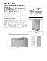
A free standing refrigerated drawer must have an anti-tip device installed as per these instructions. If the drawer is
removed from its location for any reason, make sure that the device is properly engaged when you push the drawer
back into the original location. If device is not properly engaged, there is a risk of the drawer tipping over, causing
property or personal injury if you or a child stand, sit, or lean on an open drawer.
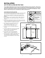
FLOOR MOUNT INSTALLATION
The anti-tip bracket can be located on the floor in the left or right
rear corner of the refrigerated drawer as shown in Figure 06.
Step by step instructions for locating the position of the
bracket:
1. Decide where you want to place the Drawer. Make a temporary
line on the floor in line with the drawer face, “A” as shown in
Figure 06.
2. At the center point where the drawer will be, draw a center line
“B” (Fig. 06) perpendicular to line “A” to the rear of the unit. Make
a mark on line “B “ 24-1/2 inches from line “A”.
3. Then make another perpendicular line “C”at
this mark. Make a mark on line “C” 11-1/2
inches from line “B” either right or left.
4. At this mark, drill 1/8” diameter pilot hole in
the floor.
5. Fasten the bracket to the floor thru the slotted
hole (see Fig. 07) using the appropriate
fasteners for the type of floor.
6. Position the unit so that the leveling leg
engages into the anti-tip bracket (Fig. 07).
7. Check for proper installation of the drawer and
anti-tip device by grasping the back of the
unit and carefully attempting to tilt the drawer
forward.
INSTALLATION
ANTI-TIP INSTALLATION INSTRUCTIONS
WARNING
• ALL DRAWERS CAN TIP
• INJURY COULD RESULT
• INSTALL ANTI-TIP
BRACKET PACKED
WITH UNIT
• SEE INSTRUCTIONS
11-1/2”
24-1/2”
23-7/8”
Center line
24”
BOTTOM VIEW OF DRAWER
Anti-tip Bracket
Refrigerated
Drawer
C
A
B
Front
11-1/2”
CEN
TE
R
LI
NE
PERP
ENDIC
ULAR
LINE
Leveling Leg
Slotted hole for
floor installation
Open slot
B
C
Fig. 06
Fig. 07
Summary of Contents for DCS RF24-D
Page 1: ...THE OUTDOOR REFRIGERATED DRAWER Use and Care and Installation Guide MODELS RF24 D...
Page 2: ......
Page 20: ...18 NOTES...
Page 39: ......

