background image

23

B

A

A

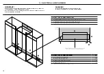
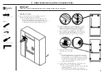
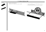
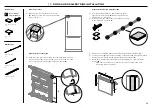
Front roller adjustment

Rear roller adjustment

Place a ruler on the 
front of the appliance to 
check flushness top and 
bottom, left and right.

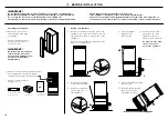
IMPORTANT!


Ensure all four corners of the appliance is supported firmly onto the floor


to eliminate any movement. 


DO NOT install the appliance on a soft, uneven, or unlevelled floor  

to avoid twisting the appliance and poor door sealing.


Raise the appliance using a 11mm hex socket or 4mm hex key. 


One turn of height adjusting nuts is equivalent to 1mm height adjustment.

Note: Maximum travel is 20mm.


If using a Powered driver, use low torque setting to avoid damaging 

the height adjustment system.


Ensure that the top, bottom and sidge gap differences are not greater 

than 1.5mm to achieve correct alignment. 


Final alignment will be achieved once door panels have been installed 

and the appliance is pushed back to sit flush with the cabinetry.

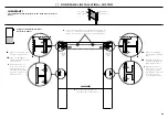
Tools

Hex key

Ruler

Powered driver (optional)

!8

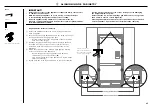
 ALIGNING INSIDE  CABINETRY

Align appliance inside the cabinetry

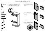
1

  Centre the appliance within the alcove, using the adjacent 

walls as a guide.

2

  Turn the front and rear adjustment nuts (A) using a hex key to 

extend the feet until it engages the floor.


– Clockwise turn raises the height and counter-clockwise 

turn lowers the height.

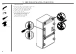
3

  Continue turning the adjusting screws alternately between 

front and rear feet to align the front of the doors top to 
bottom on both sides, and until you achieve the correct 
alignment.

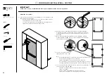
4

  Check the top and bottom, left and right gaps by placing 

a ruler on the front of the appliance.


– Ensure the gaps between appliance and adjacent 

cabinetry are even on both sides (

B

).


– This step will help ensure the appliance is level with the 

adjacent cabinetry.

5

  Gently push the front of the appliance to check the stability.

Summary of Contents for ACTIVESMART RS9120W

Page 1: ...ACTIVESMART INTEGRATED REFRIGERATOR FREEZER RS9120W models INSTALLATION GUIDE NZ AU GB IE HK SG IN...

Page 2: ......

Page 3: ...PANEL AND TOE KICK DIMENSIONS 8 CUSTOM DOOR PANEL INSTALLATION DIMENSIONS 9 CUSTOM DOOR PANEL INSTALLATION TEMPLATE 0 DOOR CLEARANCE 1 ELECTRICAL AND PLUMBING 2 BEFORE INSTALLATION 3 CAVITY PREPARATIO...

Page 4: ......

Page 5: ...pleasant taste or odor dispose of ice and refer to the flushing instructions detailed in the installation section of this user guide installation guide If unpleasant taste or odor persists you may wis...

Page 6: ...right left 2 M5 x 8 Countersunk Philips Screw M5 x 8 Countersunk Philips Screw M5x8 countersunk cross head screw 4 M5 x 10 Pan Head Philips Screw M5 x 10 Pan Head Philips Screw M5x10 cross head screw...

Page 7: ...ernal display module 1 Toe kick filter Located inside the appliance Toe kick filter 1 Miscellaneous items pack Located inside the appliance USER GUIDE NZ AU GB IE HK SG IN US ACTIVESMART INTEGRATED RE...

Page 8: ...oor panel and 1x drawer panel Custom door panel set Supplied by customer to match their cabinetry Applicable for Non water dispensing models only Non water dispensing door panel set RD9120W RD9121W Ic...

Page 9: ...l set 2134 f Overall width of cavity 914 g Overall depth of cavity 635 H Minimum cabinetry gap clearance from edge of door panels 4 I Minimum required finished return side and top cavity min 89 NOTE S...

Page 10: ...Aligns the appliance with the frame of the cabinetry Note Shown with custom panel and handle attached to fridge Note Shown with custom panel and handle attached to fridge 5 CABINETRY OPTIONS Note Dra...

Page 11: ...S mm d Height of toe kick panel 102 e Depth of toe kick measured from front of door panels 120 Note Stainless steel toe kick height 102mm is supplied with the appliance Customers need to supply their...

Page 12: ...bottom drawer panel 722 772 D Height from bottom of appliance to top of bottom drawer panel 874 E Gap between top door panel and bottom drawer panel 4 F Height of toe kick panel 102 152 G Depth of cus...

Page 13: ...9mm 2mm REF 14x Pilot holes recommended for bracket attachment Do not penetrate front surface 1016mm Ensure handle is mounted 65mm from edge of panel to the center this will avoid interference with b...

Page 14: ...ANEL RIGHT SIDE HANGING BRACKET HOLES HANGING BRACKET HOLES PRINT SPECIFICATION REVISIONS DRWN DATE CHKD ECN REV BJ 04 04 19 1 1 862945 GRAPHICS RS9120 DOOR TEMPLATE TITLE DRAWN DATE SCALE 1 1 FISHER...

Page 15: ...ccess 110 Measured from front cabinetry edge Wall 115 DOOR OPENING FULL INTERNAL ACCESS 90 DOOR OPENING Insert hinge limiting pin WARNING Before opening the doors ensure that the appliance is stable F...

Page 16: ...G A B Floor Left side of cavity Electrical and water connections must be within this space if located behind the appliance ELECTRICAL AND PLUMBING CONNECTIONS 1 Recommended location for connections in...

Page 17: ...Supply 230V 50 Hz Service 10 amp circuit PLUMBING SPECIFICATIONS Supply 13mm or 19mm BSP threaded water connection 6 35mm tubing Pressure Minimum 22 psi 150 kPa Maximum 120 psi 827 kPa 20 C Power cor...

Page 18: ...ed from the rear of the appliance during transit USER GUIDE NZ AU GB IE HK SG IN US ACTIVESMART INTEGRATED REFRIGERATOR RS90A RS9120W RS36A72 RS36A80 RS36W80 models Miscellaneous items pack Water fitt...

Page 19: ...a finished return of solid material is required across the top and sides of the new or existing alcove It is recommended that the return should be at least 89mm deep across the sides Refer to Cavity...

Page 20: ...rds the center of the back wall For 2134mm cavity installation measure 164mm downward from the projection line A For 2032mm cavity installation measure 62mm downward from the projection line B This wi...

Page 21: ...Move the appliance in front of the cabinetry close enough that you still have access behind for power and water connections A 2 Insert B the free end of the plastic water tubing fully into a water tap...

Page 22: ...the existing appliance trim Position the top trim so that screw heads in the appliance trim insert through the key holes of the brackets C 4 Slide the screws of the appliance trim towards the narrow s...

Page 23: ...doors B IMPORTANT Ensure all external packaging materials are removed from the appliance before installation Ensure the door of the appliance is closed during installation 1 2 turns B A A B Internal...

Page 24: ...se and power cord flat behind the appliance A 2 Push the appliance into the cabinetry until the anti tip bracket overlaps the rear top edge of the appliance B and the doors are in line with the cabine...

Page 25: ...d once door panels have been installed and the appliance is pushed back to sit flush with the cabinetry Tools Hex key Ruler Powered driver optional 8 ALIGNING INSIDE CABINETRY Align appliance inside t...

Page 26: ...door and drawer handles C 3 Remove the plastic plugs from the handle holes 4 per each door panel 4 Align the handle holes with the door panel holes and secure with M5x25 pan head socket screws 4 per e...

Page 27: ...to the door panel until you feel it clip securely Ensure the display is flush with the door panel A B 5 Remove water tube from the holder on the appliance door C 6 Hang the door panel onto M8 studs En...

Page 28: ...bracket B 3 Slide the forks of the side brackets onto the screws of the door C 4 Screw the M8 washer and nut to each stud D using the hex key and re tighten the side screws E to fix the door panel do...

Page 29: ...sher and M8 nut B The top of the stud must remain below the top face of the door panel 9 DOOR PANEL INSTALLATION STAINLESS STEEL 4 Secure side bracket forks by tightening side screws C Note For depth...

Page 30: ...HANGING BRACKET HOLES DRAWER PANEL LEFT SIDE DRAWER PANEL RIGHT SIDE HANGING BRACKET HOLES HANGING BRACKET HOLES RINT SPECIFICATION REVISIONS DRWN DATE CHKD ECN REV BJ 04 04 19 1 1 862945 GRAPHICS RS9...

Page 31: ...of drawer panel 1B Align left side edge of template with left side edge of drawer panel 2 Mark drill locations of screw holes for the left hanging bracket and side brackets Drill screw holes 2mm 3 32...

Page 32: ...25 pan head socket screws 4 for each handle Attach side brackets and straps E 5 Align the brackets and straps to the holes on the side of the panel and secure with M5x14 mush cross head SS screws 12 A...

Page 33: ...of the hanging bracket B 3 Slide the forks of the side brackets onto the screws of the door C 4 Screw the M8 washer and nut to the stud D and re tighten the side screws E to fix the door panel do not...

Page 34: ...hese steps to avoid difficulties in door panel adjustment and cosmetic cap fitment B A B Door panel attachment kit 8 x 16 Mush Washer Twin Thread Philips Screw 8x16 mush washer screw 1 Tools FPA spann...

Page 35: ...lly 2 Place the fixing brackets on the top and side base brackets of the appliance and secure mid way with M5x8 countersunk cross head screws A 3 Secure the center of each fixing bracket to the side o...

Page 36: ...firmly inside the casing all the way into the filter head 4 Align the filter removal tool over the filter handle and turn 90 clockwise to tighten B Remove filter removal tool and close the freezer dra...

Page 37: ...s in the correct orientation B 3 Push the grille firmly onto the appliance until the clips engage C Install the toe kick filter and grille 1 Fit the filter onto the rails and push until it clips secur...

Page 38: ...HOLES ON PLASTIC PARTS D IF TOEKICK IS HIGHER THAN 4 USE SI 1 CUT UNREQUIRED VANES FROM DOT DRILL HOLES THROUGH DIMPLES 2 USE PROVIDED SCREWS TO FIX GRILL 3 MATCHING HOLES ON PLASTIC PART H 8 With the...

Page 39: ...ss them together to form a pair E Remove the adhesive backing on one side only 4 Press firmly to the underside of the drawer top trim in the indicated locations F 5 Remove the remaining adhesive backi...

Page 40: ...C Side trim bracket Side trim TWO METHODS ARE AVAILABLE FOR ATTACHING CABINET SIDE TRIMS A FLEXIBLE SPRING CLIP METHOD RECOMMENDED METHOD B FIXED SCREW METHOD METHOD TO USE IF CABINET IS NOT TO SPECIF...

Page 41: ...spring clip correctly inserted between side trim and side trim bracket E G F 6 Open the French doors Place the assembled side trim with brackets and spring clips against the alcove side wall with the...

Page 42: ...length of 1930mm B IMPORTANT Ensure the cut is straight and square as this is an exposed surface Ensure the plastic part does not bend as this can cause visual stress marks Repeat for the remaining s...

Page 43: ...trim inwards at the locations of the top and middle side trim brackets 9 Once the trim has engaged with top and middle brackets push and engage the side trim at the location of the bottom bracket F Re...

Page 44: ...Complete and keep for safe reference Model _____________________________________________________________ Serial No _____________________________________________________________ Purchase Date ________...

Page 45: ......

Page 46: ......

Page 47: ......

Page 48: ...ifications in this document apply to the specific appliances and models described at the date of issue Under our policy of continuous appliance improvement these specifications may change at any time...

Reviews: