ROBO TX ElectroPneumatic
COMPUTING
15
Pinball machine
Now you can play pinball!
Build the model according to the assembly
instructions and wire the electrical and pneu-
matic components according to the circuit
diagram. During assembly pay attention
to accuracy when installing the parts,
connecting the hoses and wiring the
electrical components. This eliminates
the need for trouble-shooting when you
put the model into operation.
l
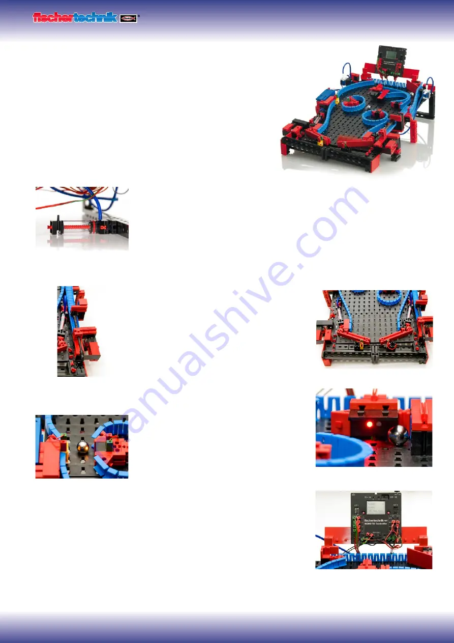
Before starting to program the model, here is further technical information on the
cylinder below the model as well as additional actuators and sensors. The cylinder is
used as a storage reservoir for air, to ensure that enough air is available to move the
cylinders when the flipper buttons are pressed quickly one after the other.
l
The ball can be shot into the playing field by a spring mechanism on the right side of
the model. This works according to the same principle as a real pinball machine.
l
The two buttons at the left and right lower
edges serve for electrical control of the two
valves for the built-in cylinders. These control the
two flipper arms. A light barrier detects when a
ball drops through the middle gap or runs past
an incorrectly positioned flipper arm. This light
barrier also serves later for counting the balls
planned for one game.
l
Another light barrier and the color sensor serve
to keep the score . The light barrier records when
the ball passes through and the color sensor mea-
sures the distance between the color sensor and
ball. This is explained in greater detail later in the
program explanation.
l
The ROBO TX Controller display serves to
indicate the score and number of balls remaining.
The display can be controlled with the two red
buttons.
Pinball control
Color sensor for proximity measurement
Measured value logging and output
Cylinder as air reservoir
Ball launching pad
Light barrier for detecting passage
Summary of Contents for COMPUTING ROBO TX ElectroPneumatic
Page 1: ......


