3
and also by the optional transmitter output. The output of
sensor 2 is used only by limit switch 2.
4.
Installation
The electronic module is mounted on a flat plate or panel,
for which it has 4 holes at the rear for self-tapping screws
3.5 mm. A wall-mounting rear adaptor plate is available
as an option (s.13. Ordering Code).
The pressure transmitter is factory calibrated while
mounted vertically, pressure ports downward. However,
it can be mounted in any orientation. If it is installed with
any orientation other than vertical (pressure ports down-
ward), the zero point must be re-set (s. 5.3.3.).
IP65 protection for the housing is guaranteed only if sui-
table connecting cable is used.
4.1.
Process Connection
Only qualified technicians authorized for this type of
work should undertake installation.
Ensure that process equipment and pressure lines
are at atmospheric pressure before making pressure
connections.
The instrument should be provided with suitable pro-
tection against pressure surges (e.g., snubber or pul-
sation damper).
Ensure that the mechanical configuration and materi-
als of construction of the instrument are compatible
with the process media.
Ensure that process pressure is always less than the
specified safe pressure rating.
Carefully check the pressure-tightness of all pressure
connections before start-up.
4.2. Electrical Connection,
Safety Precautions for
Explosion Prevention
•
Only qualified technicians authorized for this type
of work should undertake installation.
•
Switch off electrical power to the plant before at-
tempting electrical installation work of any kind.
•
Do not disconnect plug live wire.
•
To ensure safe operation supply wiring system
must meet specifications for zone 22, class 3.
Electrical connections must comply with relevant
international and local regulations and norms re-
lating to electrical and instrumentation installati-
ons in hazardous areas (e.g.: EN 60079-14,
EN 50014).
•
Operating supply voltage (24 V DC/AC) must not
excess 32 V DC/AC - neither per temporary inter-
ferences! Supply wiring system must be protec-
ted by Si 315 T.
•
For recommended current supply see 11. Specifi-
cations.
•
Parametrisation by PC serial interface adaptor
EU03.F300 is permitted only in safe areas outside
explosion-hazardous areas zone 2.
5.
Commissioning
Power supply and signal cabling to the instrument
must be correctly selected to meet operational requi-
rements and installed in a way that does not cause
physical stress to the instrument.
Pressure lines must have a downward gradient throu-
ghout from the pressure instrument to the process
vessel / pipe. This is to prevent formation of air / gas
pockets (for liquid applications) and liquid plugs (for
air / gas applications). If this continuous downward
gradient cannot be provided for any reason, then sui-
table water and / or air separation devices must be in-
serted into the pressure lines.
Pressure lines must be kept as short as possible and
must not have short bends to avoid measurement er-
rors induced by pressure line delays.
5.1.
Pressure Connections
The instruments pressure ports are marked by " " and
" " symbols. For differential pressure applications the " "
port must be connected to the higher pressure and the
" " port should be connected to the lower pressure.
If the pressure transmitter is subjected to pressure when
it is started up, zero point checking and adjustment is not
possible. In such cases, only electrical connections of the
instrument should be made, but not the pressure connec-
tions.
5.2.
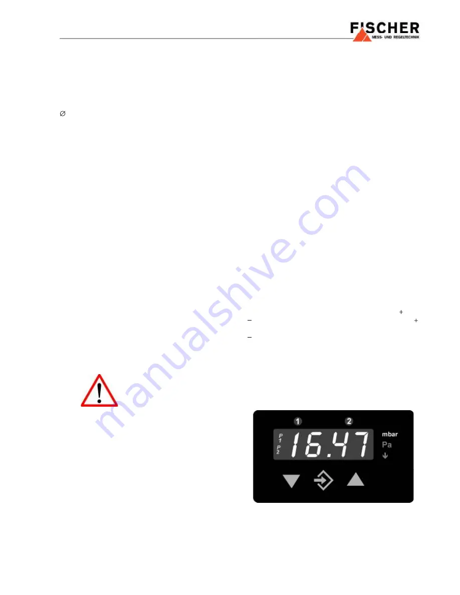
Display
The 3½ digit LED display normally indicates the current
differential pressure. The backlit symbols P1 and P2 to
the left of the 3½ digit LED display indicate the display
function (s. 5.3.2.). The backlit symbols to the right of the
3½ digit LED display indicate the unit of pressure measu-
rement. (Note: the units shown in the illustrations of this
document can be different from those of the actual instru-
Contact: EK Engineering (India)
Web: www.ekeindia.com
Email: [email protected]


