FISCHER Mess- und Regeltechnik GmbH
EU Declarations of conformity | 8
BA_EN_DA01_VUW
31 / 32
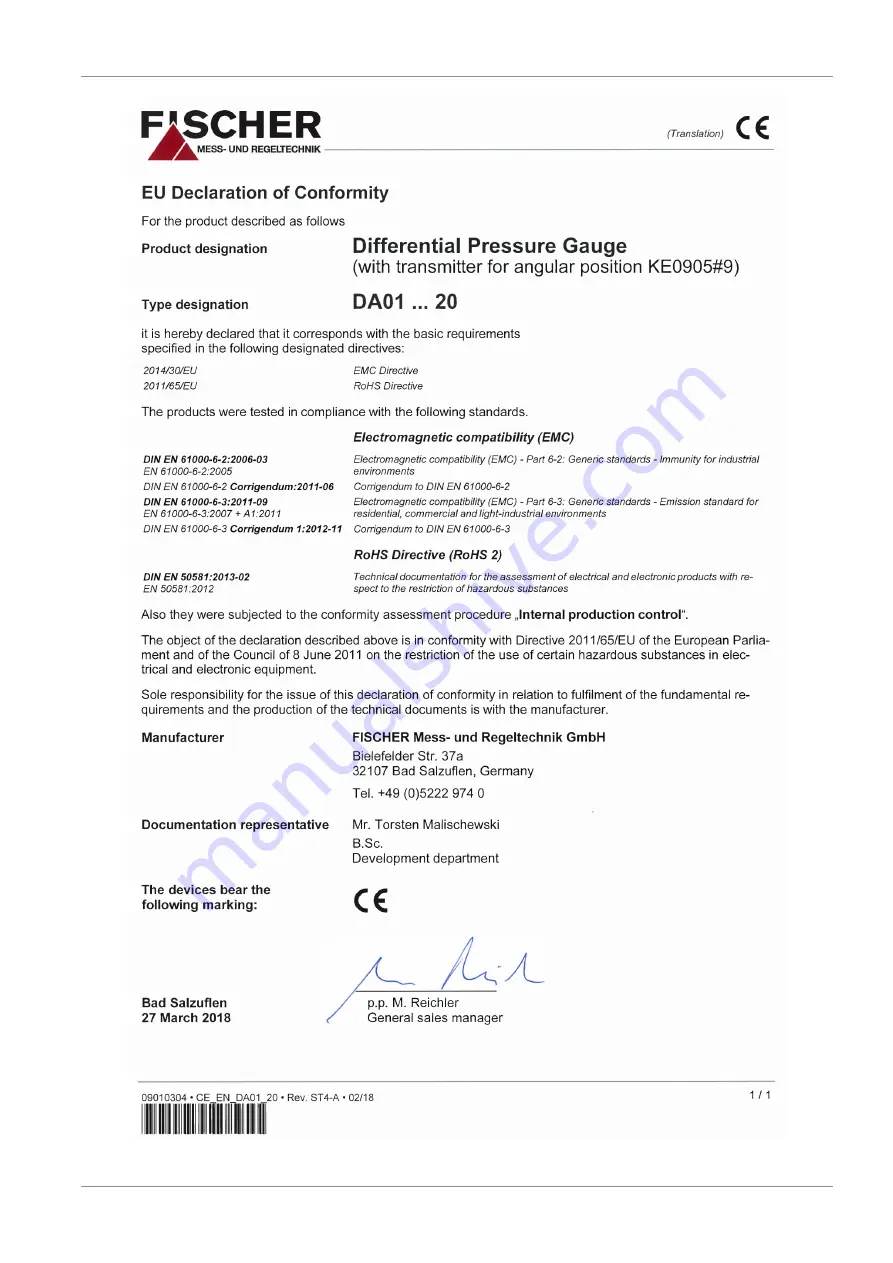
Fig. 30:
CE_EN_DA01_20
Page 1: ...Operating manual DA01 VUW Differential pressure measuring device Pressure levels PN250 PN400 Standard version 09015042 BA_EN_DA01_VUW Rev ST4 A 02 18 09015042 ...
Page 2: ...d using electronic sys tems or any other form print photocopy microfilm or another process without the written consent of the company FISCHER Mess und Regeltechnik GmbH Bad Salzuflen Reproduction for internal use is expressly allowed Brand names and procedures are used for information purposes only and do not take the respective patent situation into account Great care was taken when compiling the...
Page 3: ...oduct and functional description 6 2 1 Delivery scope 6 2 2 Equipment versions 6 2 3 Function diagram 11 2 4 Design and mode of operation 11 3 Assembly 12 3 1 General information 12 3 2 Process connection 12 3 3 Electrical connections 13 4 Commissioning 15 4 1 General 15 4 2 Venting of the pressure lines 15 4 3 Zero point correction 16 4 4 Switch point setting 16 5 Servicing 17 5 1 Maintenance 17 ...
Page 4: ... of the pertinent standards 1 3 Risks due to Non Observance of Safety Instructions Non observance of these safety instructions the intended use of the device or the limit values given in the technical specifications can be hazardous or cause harm to persons the environment or the plant itself The supplier of the equipment will not be liable for damage claims if this should happen 1 4 Safety Instru...
Page 5: ...nation DANGER Type and source of danger This indicates a direct dangerous situation that could lead to death or serious injury highest danger level a Avoid danger by observing the valid safety regulations WARNING Type and source of danger This indicates a potentially dangerous situation that could lead to death or ser ious injury medium danger level a Avoid danger by observing the valid safety reg...
Page 6: ...these can be freely combined according to the order code Wherever this is not possible this is clearly stated For instance a small measuring cell with an NG160 display and a contact ele ment is also available Large measuring cell Ø130 Small measuring cell Ø75 NG100 NG160 mbar ranges bar ranges Fig 1 Device overview 2 2 1 Process connection 1 4 18 NPT 1 2 14 NPT 1 4 18 NPT 1 2 14 NPT Inner thread O...
Page 7: ... for ATEX devices KINAX 3W2 708 226D0 KINAX 3W2 708 226E0 Rotation angle encoder in accordance with data sheet KE09 Limit switch in accordance with data sheet KE Fig 3 Contact elements 2 2 4 Special functions Marker needle Trailing needle Fluid fillings Unit without contacts Paraffin oil glycerine silicon oil Unit with inductive contacts Paraffin oil silicon oil Unit with low action contacts Paraf...
Page 8: ... installation fittings can only be used in devices with a small measur ing cell Ø75 and a display in the NG100 bayonet ring casing WARNING Panel mounting set Due to the heavy weight the operator needs to install a support construction for installation of the front panel 2 2 6 Equipment features overview The following shows the configuration possibilities of the DA01 depending on the measuring cell...
Page 9: ... 1 1 5 bar 1 3 bar Snap action contacts 1 5 bar 1 2 3 Low action contacts Pressure level PN250 PN400 Fig 6 Small measuring cell Ø75 Measured value display Ø100 Measuring range Measured value display Ø160 Inductive contacts Rotation angle transducer Trailing needle Marker needle Remote seal 1 2 3 1 2 0 0 6 bar 0 1 bar 0 1 6 bar 0 2 5 bar 0 4 0 bar 0 6bar 0 10 bar 0 16 bar 0 25 bar 1 0 6 bar 1 1 5 b...
Page 10: ...mbar Snap action contacts 1 2 3 Low action contacts Pressure level PN250 Measured value display Ø100 Fig 8 Large measuring cell Ø130 Measured value display Ø100 100 250 mbar Measuring range Inductive contacts Rotation angle transducer Trailing needle Marker needle Remote seal 1 2 3 1 2 0 40 mbar 0 60 mbar 0 100 mbar 0 160 mbar 0 250 mbar 0 400 mbar 40 60 mbar 60 100 mbar 100 150 mbar Snap action c...
Page 11: ... the separat ing and measuring membrane is filled with a pressure transfer fluid During pressure equalisation the two measuring membranes are in an idle pos ition In case of pressure difference the force acting on the membranes causes it to be moved towards the side of the lower pressure The connecting rod transfers the deflection of the measuring membranes onto the transfer lever mounted to the m...
Page 12: ...offset correction To ensure safety during installation and maintenance we recommend installing a suitable shut off valve on the system see accessories 3 2 Process connection By authorized and qualified specialized personnel only The pipes need to be depressurized when the instrument is being connec ted Appropriate steps must be taken to protect the device from pressure surges Check that the device...
Page 13: ...sconnect the system from the mains before electrically connecting the device Install the consumer adapted fuses Do not connect the connector if strained Only devices with contact elements are connected to the electrical supply To this end there is a cable socket on the side of the device or a HAN plug in the power plant version 3 3 1 Cable socket HAN plug 1 2 3 4 5 6 M20 x 1 5 Fig 12 Cable socket ...
Page 14: ... middle target Contact 3 right target 1 2 3 4 1 2 Eb 5 25V Fig 15 Inductive contacts Inductive contacts In the case of inductive contacts the switch function is not only determined by the slot type initiator but also by the switch amplifier Up to max two contacts can be used There are assigned to the target indicators as follows Contact 1 left target indicator Contact 2 right target indicator 3 3 ...
Page 15: ...o do this turn the venting screw anticlockwise as far as it will go Venting screw Closing screw 0 8 x 4 Fig 17 Venting valve 4 2 Venting of the pressure lines WARNING Risk connected to pressure Never remove the venting screw if the unit is still pressurised Close the shut off valves of the flanged fittings or depressurize the system The pressure lines need to be vented for before commissioning on ...
Page 16: ... Switch point setting There is an adjustment lock attached to the front pane of the measuring unit on units with contact elements This means that the contacts attached to the target indicators can be set to any point along the scale To facilitate switching precision and the service life of the mechanical measur ing system the switching points should lie between 10 and 90 of the meas uring range 1 ...
Page 17: ... protected against impacts It should be transpor ted in the original packaging or a suitable transport container 5 3 Service All defective or faulty devices should be sent directly to our repair department Please coordinate all shipments with our sales department WARNING Process media residues Process media residues in and on dismantled devices can be a hazard to people animals and the environment...
Page 18: ...erature DA01 U PN400 Ø75 Measuring ranges 0 0 6 bar to 0 25 bar Remote seals It is possible to attach remote seals for all measuring ranges The re mote seals need to be designed for the displacement volume the length of the cable and the application temperature DA01 W PN250 Ø130 Measuring ranges 0 40 mbar to 0 400 bar Limitations Drag indicator measuring ranges 60 mbar Contacts Transmitter measuri...
Page 19: ...f the measuring range Temperature sensor 0 3 10 C Zero point adjustment 25 of the measuring range Measuring ranges Small measuring cell Ø75 Measuring range Device model V U W 0 0 6 bar 0 1 bar 0 1 6 bar 0 2 5bar 0 4 0 bar 0 6 bar 0 10 bar 0 16 bar 0 25 bar 1 0 6 bar 1 1 5 bar 1 3 bar 1 5 bar Large measuring cell Ø130 Measuring range Device model V U W 0 40 mbar 0 60 mbar 0 100 mbar 0 160 mbar 0 25...
Page 20: ...uring system R Material Material no EU AISI Pressure caps CrNi steel 1 4404 316L Separation membranes CrNi steel 1 4571 361Ti Design of the measuring system G Material Material no EU AISI Pressure caps CrNi steel 1 4404 316L Separation membranes Hastelloy C276 Process connection Material Material no EU AISI Connecting piece and port CrNi steel 1 4404 316L Cutting ring screw connections CrNi steel ...
Page 21: ... in order to avoid condensation forming if used outdoors the casing can be filled with the following fluids depending in the type of contacts in stalled without contacts Glycerine silicon oil Low action contacts Silicon oil Magnetic spring contacts Silicon oil Inductive contacts Paraffin oil Rotation angle transducer no filling possible 6 4 1 3 Marker needle A settable red marker can be attached t...
Page 22: ...e pin assignment depends on the ordered mode and is stated in the data sheet KE or KE09 Cable socket HAN 7D Fig 21 Cable socket Cable socket Number of screw terminals 6 2PE Rated current See data sheet KE Rated voltage 250 V Cable diameter up to 1 5 mm2 with wire protection Cable screw connection M20 x 1 5 terminal range 7 13 mm HAN 7D No of crimp contacts 7 PE Rated current See data sheet KE Rate...
Page 23: ... 90 80 86 5 132 with installed contacts 112 213 with installed contacts 165 113 NG100 Ø101 NG160 Ø161 Ø9 41 3 54 4 80 132 152 R 6 Ø 9 Cable socket G 7 16 UNF Fig 22 Dimensional drawing Small measuring system Ø75 Round steel bracket 2 pipe DN50 2 pipe mounting Pipe mounting plate Spacer sleeve Attachment kit for round steel bracket possible for all models The pipe assembly set is also available as ...
Page 24: ... NG100 Ø101 NG160 Ø161 with installed contacts 7 16 UNF G 54 4 41 3 Cable socket Fig 24 Dimensional drawing Large measuring system Ø130 Installation of front panel type 1 d2 d1 d 3 1 2 0 d 4 d1 NG100 d2 d3 d4 101 132 116 4 8 Front ring Bayonet ring with connecting bracket Holding plate Assembly bracket The front plate thickness must be min 2 mm only small measuring system Ø75 and NG100 display Fig...
Page 25: ...ing bracket The front plate thickness must be min 2 mm A suitable steel construction must be used to ensure that the front plate can bear the weight of the DA03 Examples d2 d1 d 3 1 2 0 d 4 d1 NG100 NG160 d2 d3 d4 101 132 116 4 8 161 196 178 5 8 Assembly on a mounting plate Mounting to a 2 pipe Fig 26 Installation of front panel with front ring ...
Page 26: ... 90 NG160 120 NG100 138 NG160 167 5 100 18 118 Fig 27 Dimensional drawing contact devices Shut off fitting 147 155 Cutting ring connection G3 8 for 12 mm pipe DA03 Process 1 2 3 2 1 3 110 Valve open 108 54 Connection clearance 7 3 with inner spindle thread M10 42 Fig 28 Shutoff valve DZ3600SV2700 ...
Page 27: ...alue display contact elements Electrical connection Assembly Type Measuring range Code no Device model 1 Pressure level Measuring cell V PN250 Ø75 U PN400 Ø75 W PN250 Ø130 Measuring range Small measuring system Ø75 2 3 Measuring range Device model V U W 01 0 0 6 bar 02 0 1 bar 03 0 1 6 bar 04 0 2 5bar 05 0 4 0 bar 06 0 6 bar 07 0 10 bar 08 0 16 bar 09 0 25 bar 32 1 0 6 bar 33 1 1 5 bar 34 1 3 bar ...
Page 28: ...lloy C276 Process connection 5 6 03 Flange connection based on DIN EN 61518 with internal thread G 04 Connecting piece G with inside thread 1 4 18 NPT 05 Connecting piece G with inside thread 1 2 14 NPT 13 Connection shanks G with external thread G 14 Connecting port G with outer thread 1 4 18 NPT 15 Connecting port G with outer thread 1 2 14 NPT 27 Cutting ring connection in brass for 12 mm pipe ...
Page 29: ... measuring ranges achieve is re quired to activate a contact element or a drag indicator Please also note the in formation about the equipment features 8 7 1 accessories Order no Planned measures Material DZ3600SV2700 Triple valve block DN5 PN420 Flange connection acc to DIN EN 61518 Cutting ring screw connections 12 mm pipe Including assembly set 1 4571 Order no Planned measures Type 05003065 Iso...
Page 30: ...8 EU Declarations of conformity FISCHER Mess und Regeltechnik GmbH 30 32 BA_EN_DA01_VUW 8 EU Declarations of conformity Fig 29 CE_EN_DA01_10 ...
Page 31: ...FISCHER Mess und Regeltechnik GmbH EU Declarations of conformity 8 BA_EN_DA01_VUW 31 32 Fig 30 CE_EN_DA01_20 ...
Page 32: ...9 EAC Declaration FISCHER Mess und Regeltechnik GmbH 32 32 BA_EN_DA01_VUW 9 EAC Declaration Fig 31 ЕАЭС N RU Д DЕ АЛ16 В 77754 ...