6
STEP 8:
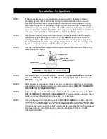
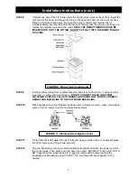
Connect one end of the 3/8” brine line to the control valve quick connect fitting. Insert the
other end of the brine line through the hole in the brine tank and into the quick connect
fitting on the safety brine valve. Remove the quick connect collet retainer clip (if
included) before inserting the brine line into each fitting, press the tube in very firmly and
replace the retainer clip behind the collet.
NOTE: THE BRINE TUBING SHOULD BE
INSERTED 5/8” INTO THE FITTING. DO NOT PUT SALT INTO THE BRINE TANK AT
THIS TIME.
STEP 9:
Install overflow tubing from overflow elbow on brine tank to floor drain. Tubing must be
lower than overflow elbow at all times.
DO NOT CONNECT DRAIN LINE FROM
SOFTENER CONTROL VALVE TO BRINE TANK OVERFLOW. DO NOT CONNECT
BRINE TANK DRAIN LINE TO THE SOFTENER DRAIN LINE.
STEP 10:
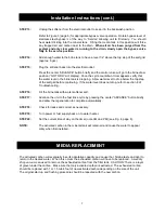
Place bypass valve in the “Bypass” position (refer to Figure 3 below). Open main supply
valve or turn on power to pump on private well systems.
STEP 11:
Fill the filter tank with water through the fill port using a garden hose or bucket. Replace
the fill port screen and fill port cap securely.
STEP 12:
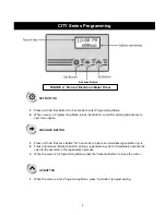
Plug the transformer into an un-switched electrical outlet and attach the power cord into
the control valve. Then press and hold down the center “ADVANCE” button until “GO TO
BW
” appears on the screen (see Fig. 4, page 8). Wait until the valve reaches the
backwash position before going to STEP 13 (a countdown timer will appear on the
display).
FIGURE 2: Brine Tank Components
FIGURE 3: Stainless Steel Bypass Valve
Operation
Installation Instructions (cont.)


