background image

Copyright Notice


This document is copyrighted, © 2018. All rights are reserved. No part of this 

document may be reproduced, copied, translated, or transmitted in any form or by 
any means without the prior written permission from Firich Enterprise Co., Ltd. 
Information provided in this manual is intended to be accurate and reliable. 
However, Firich Enterprise Co., Ltd. assumes no responsibility for its use, nor for 
any infringements upon the rights of third parties, which may result from its use.  
 

The material in this document is for product information only and is subject 

to change without notice. While reasonable efforts have been made in the 
preparation of this document to assure its accuracy, Firich Enterprise Co., Ltd., 
assumes no liabilities resulting from errors or omissions in this document, or from 
the use of the information contained herein.
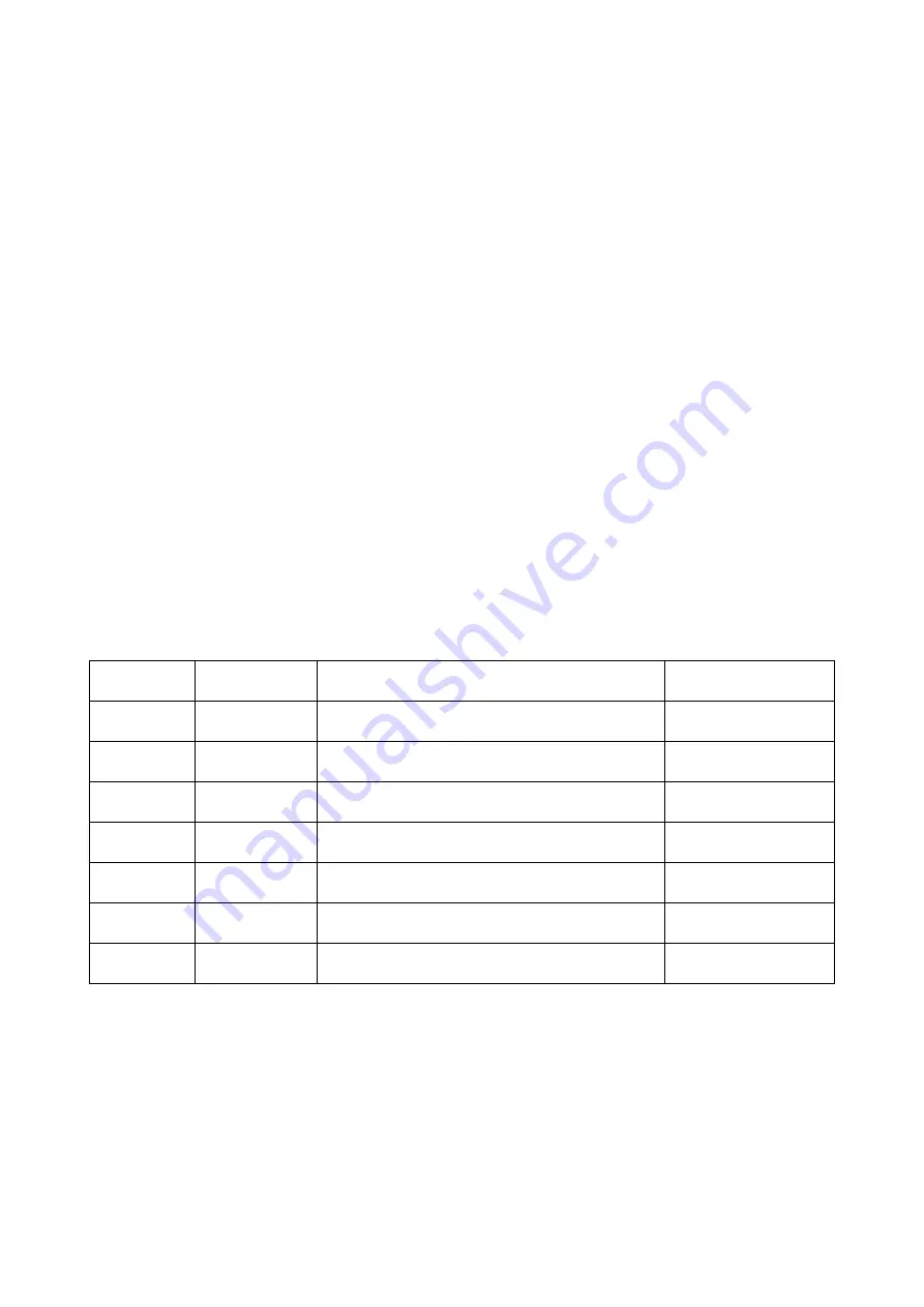


Revision Record 


Date 

Version 

Description 

Note 

2019.11.29 

0.1 

PM Initial 

Sabrina 


Summary of Contents for XP-3125W

Page 1: ...XP 3125W XPOS User Manual XP 3125W XPOS U Us se er r M Ma an nu ua al l ver 0 1...

Page 2: ...sumes no responsibility for its use nor for any infringements upon the rights of third parties which may result from its use The material in this document is for product information only and is subjec...

Page 3: ...he equipment should be noted 7 When the equipment is not in use disconnect it from the power source to avoid damage by transient over voltage 8 Liquid into the equipment may cause fire or electrical s...

Page 4: ...ure 4 OverviewDimension 5 Adjusting XP 3125W angle 7 I O Connectivity 8 Packing List 8 2 HARDWARE INSTALLATION AND UPGRADE 9 Install 2x20 2x24 customer display 9 Install Add on Device 10 3 SOFTWARE CO...

Page 5: ...em on module with IO interface is installed inside the stand base The dual hinge stand provides the user the ability to adjust the stand and display angles making it optimal for all environments On th...

Page 6: ...CD 1920 x 1080 400nits LED PCAP Optional Side Peripheral 1 MSR 2 RFID 3 Fingerprint Optional XP 2025G 2 x 20 or 2 x 24 Customer Display Optional 2MP Camera Proximity Ambient Light Sensor Power Switch...

Page 7: ...Dimension 15 6 inch A Display Height mm 235 7 B Display Width mm 368 0 15 6 inch A Panel PC Thickness mm 24 B System Height mm 293 C Base Depth mm 231 71...

Page 8: ...Adjusting XP 3125W angle...

Page 9: ...port for 2 nd display USB USB Type A USB 2 0 USB USB Type A USB 2 0 USB 2 0 for OTG COM 1 RJ 45 RI 5v 12v select in system setting 5v Green 12v Orange COM 2 RJ 45 RI 5v 12v select in system setting 5...

Page 10: ...operly through the operating system and turn off any external devices 2 Disconnect power cord from the computer 3 Remove the top cover from panel head 4 Connect the customer display cable with the pan...

Page 11: ...Install Add on Device 1 remove plastic cover 2 plug in ID device USB and fix it via 1 x M3 screw Make sure the device voltage matches the power setting before connection...

Page 12: ...C Co on nf fi ig gu ur ra at ti io on n IO Port Power Setting 1 Find Setting into operating system desktop 2 Click Device Status you may see the options for setting on COM port and C D port 3 Choose...

Page 13: ......

Reviews: