6
© 2020 Carrier
Only after proper rod positioning should the rod be fixed by tightening the gland and the whole gas
assembly with rod inserted into the air tube.
b)
Mounting of electrical igniter rod in a pilot: unscrew the rod tip, disassemble the gland, put all gland
parts on rod, insert the rod in gas head, screw back the rod tip and then set the appropriate tip
position relative to an orifice-stabilizer assy. Now the gland can be screwed onto gas head tightly
. In
case of problems in sliding the rod through rings of fixing gland grind slightly the gland ring inner surface
or use high temperature resistant grease.
After setting the correct rod position, fasten the rod fixing gland in the gas head. Then the complete gas part
assembly can be slid into the air tube.
Do not remove the rod from fixing gland if it is not necessary as the gland rings once clamped on rod do
not allow easy rod movement.
c)
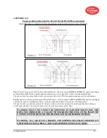
Gas part assembly and air tube should be fastened by the mounting ring thread joint. Ensure that the ring
gasket is correctly fitted in the gas head seat (see Fig. 4).
d)
The complete pilot (air tube) can be inserted into the mounting tube. In order to make the air tube slide-in
easier apply a small amount of high temperature resistant grease.
e)
The insertion depth of
SP-48-ND
pilot is determined by the design of the main burner.
If an existing pilot has to be replaced, the insertion length and pilot tip position should be the same. In case of
any doubts, the position of the pilot should be checked with the pilot and burner manufacturer.
f)
After determining the position of the complete pilot relative to the mounting tube, the mounting tube
clamping screws should be tightened to prevent the device from moving.
FIGURE 4.
Gas head with ring gasket and orifice-stabilizer assembly with bleed and main gas orifices
7.3 GAS SUPPLY INSTALLATION
a)
The pilot must be set in the mounting tube such that the gas connection is in the desired position.
b)
Connect the gas hose to the appropriate pilot input. The hose must not be tangled or twisted. If necessary,
additional connectors may be used.
c)
To ensure a long, trouble-free operation of the pilot it should be kept clean. Check the gas pipe condition
and if the orifices are not blocked. Remove all buildups. The gas hose should be dry and not cracked.
d)
During maintenance or service works, close the disconnected end of the hose with a plug or a tape.
e)
Use the automatic shutoff valves of the appropriate size and the respective closing rate and pilot gas
pressure measurement with safety interlocks (compliant with the requirements of relevant standards
concerning the shut-off safety fuel valves and burner safety) to be sure that the gas delivered to the pilot is
of an adequate pressure and can be quickly and effectively shut off.
f)
Use a manual shut-off valve on gas line for each pilot in case of maintenance or replacement and for
adjustment of pressure and flow on each pilot separately.
REMARK
: AT THE DESIGN STAGE DETERMINE LENGTH OF CABLES AND
FLEXIBLE AIR AND GAS CONNECTIONS TO ACCOMMODATE ANY EXPECTED
HEATER OR BOILER CONSTRUCTION MOVEMENT
7.4 CABLING
Wiring and electrical connections design and layout should be in accordance with the requirements for burner
installation devices specified in their instructions and the relevant regulations.


