


© 2020 Carrier
4
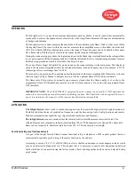
OPERATION
The InSight Series 4 scanner has numerous adjustment options available. It can be tuned either automatically
or manually to achieve the optimum level of sensitivity to the target flame balanced with superior discrimination
of background radiation.
The InSight Series 4 scanner measures the amplitude of the modulations (the flame “flicker”) that occur within
the targeted flame. The sensor within the scanner measures these amplitudes seen within either the ultraviolet
(UVS4) or infrared (IRS4) spectral ranges across a wide range of flicker frequency bands. In addition, the scanner
has a flame relay (FR) that can be related to the sensor signals in logical configurations.
During the scanner set up procedure, the logical operation for the flame relay is selected based on the settings relative
to user gain, required (flicker) frequency band and switching thresholds. Refer to commissioning procedure for more
details on set up procedures, which is selected for the desired sensor.
The current Flame Signal Strength (FS) can be viewed on the scanner display via the main menu. This displayed
value is the measure of amplitude within the selected modulation (flicker) frequency band, for example: FS=185
(Flame signal for sensors ranges from 0 to 999)
The scanner set-up procedure, the operation and settings relative to the sensor signal and the flame relay is chosen
either in Auto Config or Manual Config mode to provide the optimum flame ON/OFF discrimination.
The flame relay FR energizes its normally open contacts closed when the flame quality is at or above the
programmed flame ON threshold and remains on until the flame quality is at or below the programmed flame
OFF threshold.
IMPORTANT NOTE
-
The FAULT RELAY is energized when the scanner is powered (24 V DC) and when the
scanner has successfully passed all internal self-checking routines. The Fault relay is de-energized if there is a
power interruption to the scanner or if the scanner has detected an internal fault
.
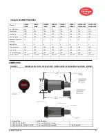
APPLICATION
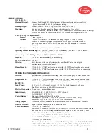
The InSight Series 4
is best suited to combustion applications that require the highest level of sophistication and
flexibility (addition choices of modulation frequencies, and the time-saving Auto Config function), and remote
Modbus communications capability (e.g. larger multi-burner boilers and furnaces).
The InSight Series 4
scanner contains either the infrared or ultraviolet flame sensor described below. The
infrared flame sensor, responds to infrared radiation from 700 to 1700 nanometers wavelength. The ultraviolet
flame sensor, responds to ultraviolet radiation from 295 to 320 nanometers wavelength.
Functional safety proof test requirements
As a part of the Insight Series 4 Flame Scanner functional safety evaluation as a SIL3 capable product there is a
requirement for periodic proof testing of the safety function by the end user.
According to section 7.4.3.2.2 f) of IEC61508 proof tests shall be undertaken to reveal dangerous faults which
may be undetected by diagnostics test. This requires that it is necessary to specify how dangerous undetected
faults which have been noted during the failure modes, effects and diagnostics analysis can be detected during
proof testing
Summary of Contents for InSight 4 Series
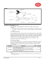
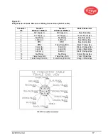
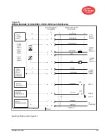
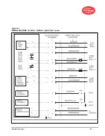
Page 19: ... 2020 Carrier 19 Figure 14 WIRING DIAGRAM 95UVS4 1 95IRS4 1 with 59 547 cable ...
Page 27: ... 2020 Carrier 27 THE MAIN STATUS MENU FIGURE 20 MAIN STATUS MENU LOOP ...
Page 36: ... 2020 Carrier 36 THE CONFIG MENU FIGURE 23 CONFIG MENU LOOP ...
Page 40: ... 2020 Carrier 40 THE AUTO CONFIG MENU FIGURE 25 AUTO CONFIG MENU LOOP ...
Page 43: ... 2020 Carrier 43 THE FILE COPY MENU FIGURE 26 FILE COPY MENU LOOP ...
Page 45: ... 2020 Carrier 45 THE 4 20 mA MENU FIGURE 27 4 20mA MENU LOOP ...
Page 47: ... 2020 Carrier 47 THE DATE TIME MENU FIGURE 28 DATE TIME MENU LOOP ...
Page 49: ... 2020 Carrier 49 THE COMMS MENU FIGURE 29 COMMS MENU ...
Page 51: ... 2020 Carrier 51 THE MANUAL CONFIG MENUS FIGURE 30 ...
Page 52: ... 2020 Carrier 52 MANUAL CONFIG MENUS continued FIGURE 31 ...