© 2020 Carrier
11
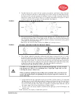
4. Consideration must be given to burner secondary air rotation, some burners have clockwise
(CW) air rotation and others have counterclockwise (CCW) air rotation. If combustion air enters
the furnace with a rotational movement of sufficient velocity to deflect the ignitor flame in the
direction of rotation, position the scanner 10 to 30 degrees downstream of the ignitor as shown
in Figure 4 and close to the periphery of the burner throat (See Figure 3).
FIGURE 4.
SCANNER LOCATION VS. SECONDARY AIR ROTATION
CCW ROTATION
CW ROTATION
5.
Having determined the approximate location for the sight pipe, cut a clearance hole for a 2 inch
pipe through the burner plate. Look through the hole. If register vanes interfere with the desired
line of sight, the interfering vane(s) should be trimmed to assure an unrestricted viewing path at
all firing levels as indicated in Figure 5.
Note: Always check with the burner manufacturer before you trim register vanes.
FIGURE 5.
IF POSSIBLE, FLAME SHOULD COMPLETELY COVER SIGHT OPENING
NOT THIS
NOT THIS
BUT THIS
OR THIS
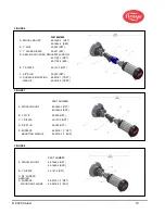
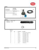
6. The preferred method for mounting surface mounted scanners requires the use of a swivel
mount, P/N 60-1664-X, shown in Figures 7, 8, and 9. Center the swivel mount over the two inch
hole in the burner plate and secure using three hexed cap screws (not provided). Install the sight
pipe on the swivel mount. If a swivel is not used, insert the end of the sight pipe into the hole,
align the hole to the desired viewing angle and tack weld (welding must be adequate to temporarily
support the weight of the installed scanner). The sight pipe should be arranged to
slant downward so that dirt and dust will not collect inside.
CAUTION: Use no more than one foot of one inch diameter sight pipe. Increase the sight
pipe diameter one inch for every additional foot of sight pipe length used to avoid
restricting the scanner’s field of view.
When a satisfactory sighting has been confirmed by operational testing, secure the swivel
mount’s ball position in place by tightening the three hex head cap screws located on the
swivel mount ring.
7. In larger multi-burner type applications such as power, kiln or refinery burners, it is recognized
that there may be several obstructions within the scanner overall range of view. The same princi-
ple of adjusting the scanner such that the flame is within the center of its field of view applies.
Use of a swivel mount allows the scanner to be adjusted to target the flame within the center of
the scanner range of view. (See obstructed view in figure 6 above).
8.
For ease of use, the scanner should be installed on the sight pipe so the OLED display can
easily be read.
Note: Operation of the display is independent of position.
MAIN
BURNER
MAIN
BURNER
Summary of Contents for InSight 4 Series
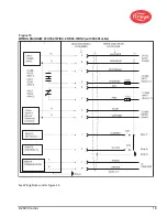
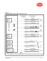
Page 19: ... 2020 Carrier 19 Figure 14 WIRING DIAGRAM 95UVS4 1 95IRS4 1 with 59 547 cable ...
Page 27: ... 2020 Carrier 27 THE MAIN STATUS MENU FIGURE 20 MAIN STATUS MENU LOOP ...
Page 36: ... 2020 Carrier 36 THE CONFIG MENU FIGURE 23 CONFIG MENU LOOP ...
Page 40: ... 2020 Carrier 40 THE AUTO CONFIG MENU FIGURE 25 AUTO CONFIG MENU LOOP ...
Page 43: ... 2020 Carrier 43 THE FILE COPY MENU FIGURE 26 FILE COPY MENU LOOP ...
Page 45: ... 2020 Carrier 45 THE 4 20 mA MENU FIGURE 27 4 20mA MENU LOOP ...
Page 47: ... 2020 Carrier 47 THE DATE TIME MENU FIGURE 28 DATE TIME MENU LOOP ...
Page 49: ... 2020 Carrier 49 THE COMMS MENU FIGURE 29 COMMS MENU ...
Page 51: ... 2020 Carrier 51 THE MANUAL CONFIG MENUS FIGURE 30 ...
Page 52: ... 2020 Carrier 52 MANUAL CONFIG MENUS continued FIGURE 31 ...


