background image

Firetide. Reliable Connectivity Anywhere

 3


Preliminary Version 1.1

Using the Mounting Bracket

  The bracket allows easy tilting and aiming of the device. It also allows the unit to be mounted with 

its internal antenna oriented for either vertical or horizontal polarization and allows mounting on 
either a horizontal or vertical pole. Note that the internal antenna polarization is vertical when the 
connectors are pointed down. A 2.4 GHz antenna is built in to the unit. There is also an external 
antenna connector. Keep the plastic cover on this connected to prevent water from getting into 
the unit.

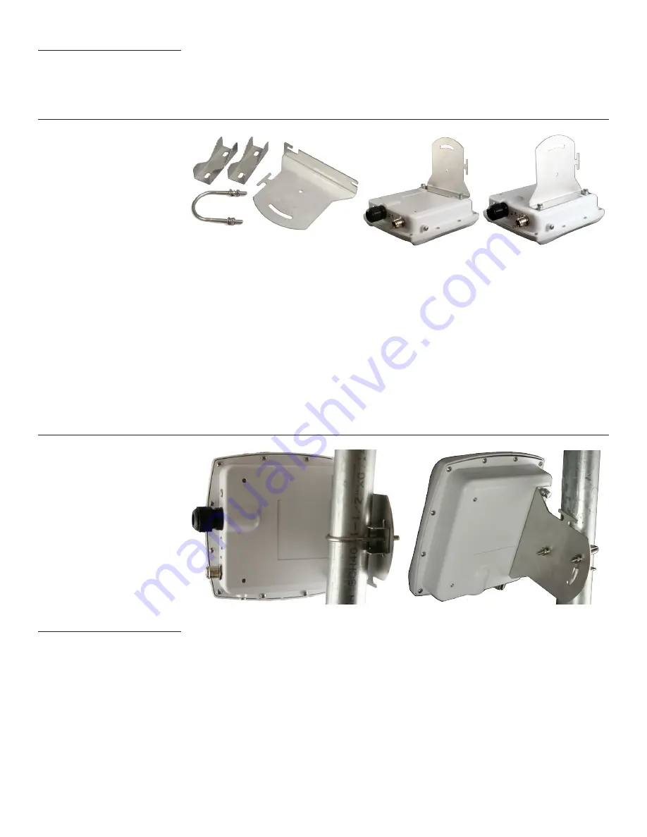
Figure 2.  FWB-100 Mounting Bracket


In order to avoid climbing up and down the pole twice, power up the unit before proceeding with 
the installation. The only connection you need is the Ethernet; it provides power as well.


Attach the bracket to the back of the unit, using the two slotted holes shown on the right side of 
the bracket, as shown in Figure 2. Select two holes on the unit according to the desired orientation 
of the pole and the antenna. 


The bracket is attached to the pole using the U-bolt and one or two of the supplied jaw-clamps 
(Figure 3). One jaw-clamp is used between the bracket and the pole; the second clamp may be used 
on smaller-diameter poles by placing it over the U-bolt before putting the U-bolt around the pole.


After placing the U-bolt around the pole, place the bracket over the legs of the U-bolt such that 
one leg passes through the round hole and the other leg passes through the curved slot. Snug the 
bracket slightly with the supplied nuts and lockwashers, but do not tighten until you have aligned 
the unit. The result should resemble Figure 3.

Figure 3.  U-bolt Mounting Assembly; Tilting the Unit for Signal Alignment


Aligning the FWB

  The Alignment LED provides a visual indication of signal strength. Point the FWB in the direction 

of its signal source, then carefully adjust it, both horizontally and vertically, using the Alignment 
LED as a guide. The LED will blink more rapidly as the signal strength increases. When you receive 
the strongest signal, tighten the nuts. Figure 3 shows how the bracket can be used to tilt the unit.


The LED alignment feature is enabled by default. To insure maximum performance, you should dis-
able the feature via the web interface after installation is complete. If you are re-aligning anten-
nas, be sure to re-enable the alignment feature.

Summary of Contents for FWB-100

Page 1: ...7 Preliminary Version 1 1 The contents of this User Guide are subject to change without notice Please refer to the Firetide partners web site partners firetide com for current versions User Guide FWB 100 Wireless Bridge ...

Page 2: ...rom the unit to the location where you will connect with other equipment The cable must be a 4 pair cable smaller cables will not seal in the waterproof connector The cable can be pre terminated the waterproof connector will pass an RJ 45 plug Figure 1 FWB 100 Package Contents Power Injector Connectors Assembling the Ethernet Cable Test the unit before mounting it on the pole or mast Begin by maki...

Page 3: ...t and one or two of the supplied jaw clamps Figure 3 One jaw clamp is used between the bracket and the pole the second clamp may be used on smaller diameter poles by placing it over the U bolt before putting the U bolt around the pole After placing the U bolt around the pole place the bracket over the legs of the U bolt such that one leg passes through the round hole and the other leg passes throu...

Page 4: ...odes are paired or married at the factory Within each pair the unit with the lower serial number is assigned IP address 192 168 224 161 and the unit with the higher serial number is as signed IP address 192 168 224 162 You can change these addresses if desired Configure the computer to have an IP address on the subnet 192 168 224 0 24 When you power up the two units on the bench they will usually ...

Page 5: ...0 to 9 miles 0 to 14 5 km Click Apply to save settings Link Basic Settings Link Basic Settings include Multicast Data Rate Fragmentation Threshold and Management VLAN Settings The data rate can be set from 1 Mbps up to 54 Mbps Fragmentation threshold is gener ally left at the default setting of 2346 Management VLAN status can be enabled or disabled When enabled select the appropriate management VL...

Page 6: ... Radio Settings Radio settings used by the node are displayed on this page Node settings for Modulation Data Rate and Transmission Power can be selected Click Apply to save settings Advanced Radio Settings Advanced radio settings allow you to select the active antenna If you are using an external 5 GHz antenna e g you purchased the FWB 105 package you must set Select Active Antenna to External Ant...

Page 7: ...g Save Nodes can be restored by using the Restore function to apply a previously saved file System Commands System Commands let you reboot the Appliance or perform a factory reset Note that a factory reset will re enable the antenna alignment tool and require you to re specify the country code Antenna Alignment Antenna alignment settings are available here Alignment is on by default To insure maxi...

Page 8: ...Refresh to see the current status Link status includes current radio operating mode RF channel node MAC addresses and IP addresses The Manage Remote but ton lets you connect to and manage the remote node as long as the RF link is up Node Status Node Status is displayed here Click Refresh to see the current status ...

Page 9: ...firmware you must have Java installed on your PC When you begin this pro cess the Java applet will take a moment to load Browse to select upgrade image Click Start Upgrade to begin Once started the upgrade can be cancelled by clicking Cancel Upgrade Logout Select the Logout tab to securely exit from the session ...

Page 10: ...9 12 18 24 36 48 54Mbps Network Standards IEEE 802 11a b d g e f h i Transmit Power Control TPC capable in conjunction with Firetide Software application Security Encryption WPA 64 128 256 w TKIP AES IEEE 802 1x LEAP Regulatory Certifications Contact your Firetide dealer for product availability and certifications for your country Specification FWB 102 FWB 105 Network Port One 10 100 Mbps Ethernet...

Page 11: ...cuit different from that to which the receiver is connected Consult the dealer or an experienced radio TV technician for help FCC Radiation Exposure To ensure compliance with the FCC s RF exposure limits the antenna used for this transmitter must be installed to provide a separation distance of at least 70 cm from all persons and must not be co located or operated in conjunction with any other ant...

Page 12: ...ct to change without notice Firetide HotPort and HotPoint are registered trademarks of Firetide Inc Reliable connectivity anywhere HotView HotView Pro MeshBridge and AutoMesh are trademarks of Firetide Inc In no event will Firetide be liable for any special incidental consequential punitive or indirect damages whatsoever including without limitation damages for loss of profits business interruptio...

Reviews: