background image

REV. 1-8-18  Page 5

Line of Fire - TMSI Series Fire Pits

Model:

MT Natural Gas (NG)

NG Factory 

Orifi ce

BTU’s

Natural

LP Factory 

Orifi ce

BTU’s 

Propane (LP)

LOF-30LHTMSI-N

#18 (4.3mm)

65,000

#40 (2.49mm)

65,000

LOF-36LHTMSI-N

#18 (4.3mm)

65,000

#40 (2.49mm)

65,000

LOF-30LTTMSI-N

#18 (4.3mm)

65,000

#40 (2.49mm)

65,000

LOF-36LTTMSI-N

#18 (4.3mm)

65,000

#40 (2.49mm)

65,000

Table 2

 Btu Specifi cations

Pressure

NG

LP

Min. Inlet

3.5” WC

 8.0” WC

Max. Inlet

10.5” WC 13.0” WC

Normal Inlet 7.0” WC

11.0” WC

Table 3

  Gas Pressures

Disclaimer:

 Btu listings are based on 7.0”WC for Natural 

Gas and 11.0”WC for Liquid Propane (LP) at the burner 

orifi ce.  Flex line size and proper gas pipe sizing will also 

affect Btu’s.  As a result your Btu’s may vary slightly from 

Table 2 specifi cations.

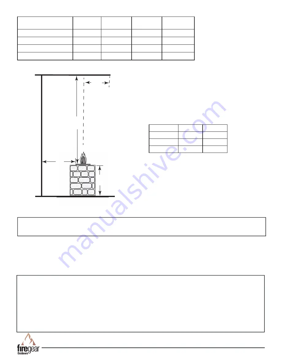
Fig. 3

 Clearance to Combustibles (Not to be used in 

an enclosed space)

Description:

  These fi re pits are designed to be installed into a non-combustible enclosure.  They are a “drop-in” style 

system to make installation quick and convenient.  Due to the length of the thermocouple wire the control panel must be 

mounted within 24” of the burnerpan.  The fi re pit uses a thermocouple manual safety ignition (TMSI) system.  This 

system has a battery operated manual Piezo ignition to light the burner, then uses a thermocouple to keep the fi re pit 

burning during operation.  If the fl ame for any reason is blown out or extinguished the thermocouple will cool down and 

shut the gas supply OFF. Media (not supplied) is required inside the burner pan for operation (See page 12).  

WARNING: 

Proper clearances from combustible materials must be maintained from all sides, top and bottom of this 

appliance.  Use the specifi cations listed on pages 4 and 5 for proper clearance to combustibles. 

Firegear Outdoors fi re pits are constructed and tested to follow the rigid ANSI standards for gas appliances and 

manufactured safely providing dependable and certifi ed products.  If these fi re pits are not installed according to the 

installation manual (i.e. not providing ventilation, not providing proper drainage, installing fi re pits below grade or 

modifying the existing products from a normal installation) Firegear Outdoors cannot be responsible if the product does 

not operate as designed.  

Modifying the fi re pit directly out of the carton will void the warranty and nullify the CSA listing it was certifi ed for. Before 

you consider creating your own custom design with a certifi ed product ensure you contact Firegear Outdoors to consult 

the installation before proceeding.   If you move forward and modify a product without consulting, Firegear Outdoors 

cannot be responsible if the product does not operate as designed.  

96”

36”

18”

C

ombustible 

Side W

all

Combustible Ceiling

Combustible Floor

CL

36”

     Max 

Overhang

Summary of Contents for LOF-30LHTMSI-N

Page 1: ... MANUAL FOR FUTURE REFERENCE INSTALLATION PRECAUTION This fire pit requires a minimum 18 square inches per side of cross ventilation Failure to provide proper ventilation can void the warranty Natural Gas Description LOF 30LHTMSI N 30 x 10 Linear Fire Pit with H Burner LOF 36LHTMSI N 36 x 12 Linear Fire Pit with H Burner LOF 30LTTMSI N 30 x 6 Linear Fire Pit with T Burner LOF 36LTTMSI N 36 x 6 Lin...

Page 2: ... other appliances Any LP cylinder not connected for use shall not be stored in the vicinity of this or other appliances WARNING Do not leave unattended during use Do not use for cooking Follow all gas leak procedures in this manual prior to operation WARNING Improper installation adjustment alteration service or maintenance can cause injury or property damage Read the installation operating and ma...

Page 3: ...pervious to all weather conditions if not protected See the accessory page for information and sizes All media i e lava rock lava stones lava boulders and fire glass has the potential of thermal spalling This is a process that may occur when media is wet and moisture gets trapped inside of the material due to rapid temperature differences When this happens the media has the potential to crack or p...

Page 4: ...P WIDTH H LOF 30LHTMSI N 30 x 10 762 x 254mm 26 660mm 12 318mm 32 826mm 2 57mm 2 64mm 10mm 1 32mm LOF 36LHTMSI N 36 x 12 914 x 305mm 32 813mm 14 368mm 38 978mm 2 57mm 2 64mm 10mm 1 32mm LOF 30LTTMSI N 30 x 6 762 x 152mm 27 686mm 8 216mm 32 826mm 2 57mm 2 64mm 10mm 1 32mm LOF 36LTTMSI N 36 x 6 914 x 152mm 33 838mm 8 216mm 38 978mm 2 57mm 2 64mm 10mm 1 32mm A B C D F E G H A Fig 1 H style burner pan...

Page 5: ... the fire pit burning during operation If the flame for any reason is blown out or extinguished the thermocouple will cool down and shut the gas supply OFF Media not supplied is required inside the burner pan for operation See page 12 WARNING Proper clearances from combustible materials must be maintained from all sides top and bottom of this appliance Use the specifications listed on pages 4 and ...

Page 6: ...d the pipe with weather sealant 3 The primary gas shut off not supplied will require a male flared fitting to enable connection of the stainless steel flex gas line supplied with the fire pit see Fig 6 page 9 IMPORTANT Installation of Natural or LP gas should be done by a qualified installer service agency or gas supplier This appliance must be isolated from the gas supply piping system by closing...

Page 7: ...es required for the amount of BTU s for a new gas line installations If you are using an existing gas line you must take into consideration the existing gas line capacities to ensure you will have proper pressure This chart is for reference only we recommend you consult with a Licensed Plumber Gas Fitter or NFPA54 National Fuel Gas Code current edition for more details Length of Pipe in Feet 1 2 3...

Page 8: ...se only Not approved for any indoor use 8 This fire pit is designed to have Firegear Outdoors lava rock or glass media completely covering the burner tube so that the burner is not visible Do not cover more than 1 above the top of burner Use lava rock a minimum of 1 diameter as a base to fill the burner pan DO NOT USE STONE OR RIVER ROCK 9 Gas lines and fittings must be installed in to the non com...

Page 9: ...OTE Gas shut off is not supplied OFF OFF ON OFF LOW HI 1 Unscrew counterclockwise red ignitor knob button and remove 2 Insert AA battery negative end into the ignitor battery compartment 3 Install clockwise red ignitor knob button 2 Insert AA Battery 1 Remove Ignitor Knob Button 3 Install Ignitor Knob Button INSTALLING BATTERY INTO PIEZO IGNITOR Fig 7 Piezo ignitor battery installation ...

Page 10: ...ent burners and circulating air passageways of the appliance be kept clean 5 Inspect the fuel supply connection before each use of the appliance 6 Temporary storage of this appliance indoors is permissible only if it has been disconnected from its fuel supply Natural or L P gas line WARNING 1 This appliance is hot when operated and can cause severe burns if contacted 2 Do not burn any solid fuels ...

Page 11: ...REV 1 8 18 Page 11 Line of Fire TMSI Series Fire Pits TMSI REPLACEMENT PARTS 1 2 6 3 8 7 5 9 10 Drawings not to scale OFF OFF ON OFF LOW O F F O N 4 11 AA Battery 13 12 ...

Page 12: ...s 6 12 1 FG SPARK IGN 7 Manual gas valve 1 FG GASVALVE 1 8 Gas control knob only 1 FG CONTROL KNOB 9 Control panel plate only 1 FG CONTROL FP 10 Control panel includes items 6 8 9 10 11 12 13 1 FG CONTROLPANEL 11 AA battery 1 BATTAA 12 Ignitor Ignitor wire 1 FG IGNITORWIRE 13 Thermocouple only 1 FG TC 1 14 LP Conversion kit for for all 30 36 models 1 LOF BO LP40 Item Description Qty Part Number Mo...

Page 13: ...2 Ensure all gas supply lines are turned ON 3 Ensure there is not too much media overtop of burner it can inhibit gas from flowing 4 Check gas pressure 5 Ensure thermocouple is correct height Tip of thermocouple should be fully engulfed by flame and approximately 1 35mm to 1 45mm from base of bracket 6 Check thermocouple voltage Minimum voltage to operate system is 12 14mV Low flame 1 Ensure the b...

Page 14: ...ps below to proceed See Table 2 on page 5 for proper LP orifice Fig 1 Shows main burner orifice location Air Shutter Sleeve Step 6 After the main burner orifice and brass fitting is re moved then slide the air shutter sleeve off the burner tube and expose the hole for the LP gas Figs 3 4 Fig 3 Natural gas setting air shutter sleeved installed Fig 2 Shows main burner orifice Fig 4 LP gas setting ai...

Page 15: ... or service removal from the original location or re installation into another location or failure to perform normal and routine maintenance Damage due to severe weather conditions such as hail hurricanes earthquakes tornadoes discoloration due to over heating exposure to chemicals including salt either directly or in the atmosphere or very high humidity is not covered by this Limited Warranty The...

Page 16: ...REV 1 8 18 Page 16 Line of Fire TMSI Series Fire Pits NOTES ...

Page 17: ...8 18 Page 17 Line of Fire TMSI Series Fire Pits FOR TECHNICAL SERVICE CALL Firegear Outdoors 9230 Conservation Way Fort Wayne IN 46809 Sales Support 888 699 6167 WEB SITE www firegearoutdoors com 855 498 8324 ...

Page 18: ...Model Number ___________________________ 2 Serial Number ___________________________ 3 How long is the gas line run Nat Gas ____ LP Gas ____ 4 What size is gas line _____ 5 Inlet Gas Pressure _____WC Manifold Gas Pressure _____ WC 6 What type of media are you using __________________ 7 Review the troubleshooting section in the installation manual 8 What are the symptoms Please be prepared to expla...

Reviews: