background image


28 


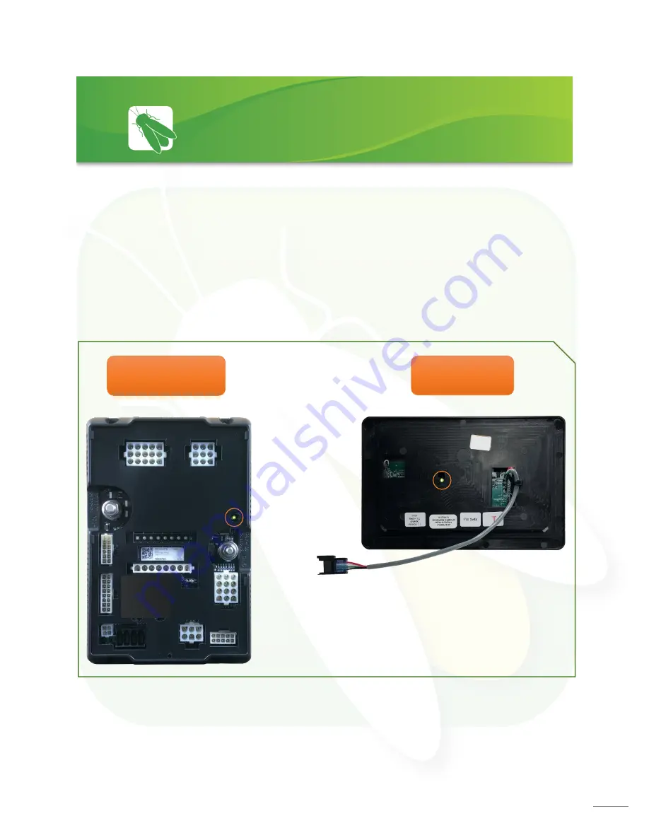
Your distribution panel and touchscreen are connected via your coach’s RV

-C network.  Each 

component will have a NET LED that is used to show network status.  If a NET LED is displaying 

anything other than solid green and some of the panel’s functions are 

not working, please 

contact your manufacturer for Technical Support.   


Net LED Locations:


Back of 

Touchscreen 

G12 Panel 

Networking 

Summary of Contents for VEGATOUCH Coach House V4

Page 1: ...1 Coach House V4 Manual ...

Page 2: ...tings 10 Settings Mobile App 11 Settings Network Diagnostics 13 Overcurrent Detection 14 Settings Switch Panel Info 15 Floorplan Selection and Options 16 Wireless Switch Pairing 17 Service Mode 18 Vegatouch Eclipse Setup 26 SSP17 Switch Panels 27 G12 DC Panels 28 Networking 29 Network Status Indicators 30 Mira NET LED Status Key 31 System Diagrams 1013 Elroy Drive Middlebury Indiana 46540 Phone 57...

Page 3: ... icon from the navigation bar to select the desired page The currently selected page will always be listed in the top corner of the screen Lyra Screen Navigation Home AGS Lights Climate Settings Navigation Menu ...

Page 4: ...hold Light Master On to turn the lights back on Slide Awning This section of the screen will toggle between the Slide control or Awning control based on the Parking Brake Ignition inputs currently being received by the G12 panel Slide Press and Hold EXT or RET to operate the Slide Awning Tap the Awning button to fully extend or retract the awning Climate Control Tap the arrows to select your desir...

Page 5: ...es The graphics will display Green while above 12V and Red while below 12V These graphics represent the percentage filled for holding tanks Water Pump Tap to toggle On Off LP percentage remaining shown disconnected 4 4 5 Generator Controls The Generator display will show the total number of generator hours accumulated as well as the current operating status running or stopped Generator hours are s...

Page 6: ...ing for the entire coach including the exterior Tap any button to turn the desired light On Off Lights with up down arrows are dimmable Press and hold these buttons to ramp the brightness up or down Tap the buttons to toggle On Off Lights ...

Page 7: ...v 12 5v Time at Start Volts The generator will start when the voltage drops to the Start at Voltage for this specific amount of time Range 5 seconds 1 minute 5 seconds 1 minute Stop at Volts The generator will shut off when the voltage reaches this set point depending on Time at Stop Volts setting below Range 13 2v 14 5v Time at Stop Volts The amount of time required for the voltage to remain at S...

Page 8: ...l automatically run to keep your desired temperature consistent Furnace may be selected manually to be used in addition to the Heat Pump Vent Fan Controls Tap Power to raise the lid and start the fan at medium speed Tap a speed selection if you d prefer it to run faster or slower Tap Lid Down to power off the fan and close the lid Tapping Lid Up will raise the lid but will not start the fan Fan Mo...

Page 9: ... is enabled the screen will enter sleep mode after 60 seconds of inactivity Tap anywhere on the screen to wake it up Please note that even if Auto Dimming has been disabled the screen will still enter sleep mode after 4 hours of inactivity during daytime hours 5am 10 59pm and after 15 minutes of inactivity during night time hours 11pm 4 59am as the result of a built in screen saver that cannot be ...

Page 10: ...e that easily connects to any Android or iOS device to give total control to many electrical electronic and mechanical systems in your coach Pair any device with the coach s built in interface to monitor and control these systems Settings Mobile App ...

Page 11: ...lts the system is experiencing Tap the tabs at the bottom of the screen to visit the different diagnostic pages A red triangle will appear whenever a fault condition exists Tap it to navigate to the Network Diagnostics page for specific fault information Settings Network Diagnostics Current Faults Green Online ...

Page 12: ...12 This screen will show which G12 Outputs are currently active This screen will show the current status of the Aircons and Vent Fan Controllers Active Output Main Vent Fan Controllers Disconnected ...

Page 13: ...rief set of instructions From this screen tap Continue to navigate to the Diagnostics screen The Diagnostics screen will use red lights to alert you of overcurrent detections To clear the faults navigate to each faulted control and tap them to reset Note you ll notice that their buttons have turned red and will remain that way until cleared RED Overcurrent Fault Overcurrent Detection Tap to reset ...

Page 14: ...he screen It is likely that the battery inside your switch panel needs replaced The wireless switch panel in your coach will illuminate a green LED whenever a button is pressed If the LED on your switch panel does not illuminate when you press a button on your switch you will need to replace the 2032 coin cell battery If the LED is illuminating but the switch still won t function see the Wireless ...

Page 15: ...an box for 7 seconds to enter the Floorplan Options selection screen From here you ll be able to select the correct floorplan and any options that are specific to the coach Tap Apply to save and exit Floorplan Selection and Options ...

Page 16: ...will need to replace the 2032 coin cell battery If a new battery will not fix the issue you might need to pair the switch panel to the screen Press and Hold a switch graphic for 3 seconds until the pairing screen appears Tap Start Pairing You ll have 30 seconds to press and hold any 2 buttons on the switch panel at the same time for 5 seconds Tap Done once the pairing successful message appears It...

Page 17: ...s Switch Pairing Floorplan Selection To enable Service Mode Press and hold the Settings button for 5 seconds until a yellow wrench appears at the top right hand corner of the screen next to the time Now release your finger and the Warning screen will appear Once you tap enable the wrench will turn Red To disable Service mode tap the red wrench then tap Disable from the warning screen Service Mode ...

Page 18: ...as finished install the app and open it Press and Hold the logo for 7 seconds to switch between Mira and Eclipse if necessary Setup Tap SCAN to find the Eclipse Module s signal After scanning any Eclipse Module in your area will appear on the screen the list is scrollable Tap the ID that matches the one for your Eclipse Enter the PIN number from the Eclipse label and press AUTHENTICATE to connect ...

Page 19: ...ur location Notice Android Setup Tips Allow Vegatouch Eclipse to access this device s location Eclipse will need to be allowed access to your location Tap ALLOW when you see this screen If you do not tap allow the module will not be found in the scan Location Services Required To enable Location Services on your Android device 1 Open your phone s Settings app 2 Tap Location App Permission If you d...

Page 20: ...ich are currently paired to Eclipse Tap the trash can icon to completely remove a specific device from memory Once removed this device will no longer have remote access to the system Note you cannot remove the device that you are currently using Tap the Temperature Units selection to choose between Fahrenheit and Celsius System Information and Eclipse Name Tap to enter the Diagnostic Tools screen ...

Page 21: ...e Ball and Socket will display once connection has been made A Green Checkmark signifies that the password has been stored in memory Visit the Saved Networks page to quickly connect to previously used networks Tapping Update Config will force a download of the config from the cloud 1 a a a a a a a 2 a a a a a a a 2 a a a a a a a 1 a a a a a a a 3 a a a a a a a 3 a a a a a a a 4 a a a a a a a 4 a a...

Page 22: ...u d prefer to use an ethernet connection exclusively Disconnect from Eclipse Tap YES if you d like to disconnect from Eclipse Note before you can connect remotely you ll need to pair locally to authenticate your device System Information and Eclipse Name 1 a a a a a a a 1 a a a a a a a System Information and Eclipse Name 2 a a a a a a a 2 a a a a a a a ...

Page 23: ...tween a Local and Remote location The Local Remote switch page can also be reached by tapping Local or Remote on the top bar System Information and Eclipse Name 1 a a a a a a a 1 a a a a a a a 1 a a a a a a a Tap to update the config from the cloud ...

Page 24: ...24 Diagnostics Tap to display a list of currently connected devices Remote Help is available by contacting Firefly Integrations Do not enable Remote Help without consultation ...

Page 25: ...set a custom pin number Tap to completely reset the device A warning page will appear which will require you to confirm the action System Information and Eclipse Name 1 a a a a a a a 2 a a a a a a a 1 a a a a a a a 2 a a a a a a a ...

Page 26: ...ireless RF technology to communicate with the Lyra touchscreen These switches are powered by a 2032 coin cell battery If you press a switch panel button and the operational LED does not illuminate you ll need to change the battery Simply use your fingers to pry the switch panel away from the wall mounted backplate to access the battery compartment on the back of the switch Once you replace the bat...

Page 27: ...and listed on a black label load list which is usually mounted next to the G12 panel Troubleshooting Example If you press the Front Accent Lights button on your Lyra screen and the lights don t come on check the Network Diagnostics Page to see if the light for Output 27 shows status If it does you will want to check output voltage on that pin to make sure that the G12 is sending power to the light...

Page 28: ...ch component will have a NET LED that is used to show network status If a NET LED is displaying anything other than solid green and some of the panel s functions are not working please contact your manufacturer for Technical Support Net LED Locations Back of Touchscreen G12 Panel Networking ...

Page 29: ...shing Green Light 1 time sec Device was online but has been offline for at least 5 sec Solid Green Device is connected to network and is communicating properly Solid Red Device has gone offline and is not connected to a network Alternating Red Orange Device has gone offline and is trying to re connect within 30 sec Alternating Green Orange Device is currently online but has gone offline 2 or more ...

Page 30: ...e past 60 seconds and good files Fast alternating green and blue 4 times sec Device is attempting to make initial connection to the CAN network and corrupted files Solid blue Device is operating correctly and has seen a CAN message in the past 5 seconds and corrupted files Slow alternating green and blue 1 time sec Device was active on the CAN bus but has not seen a valid message in 5 seconds and ...

Page 31: ...31 ...

Page 32: ...32 ...

Page 33: ...33 ...

Page 34: ...34 ...

Page 35: ...35 ...

Page 36: ...36 ...

Page 37: ...37 ...

Page 38: ...38 ...

Reviews: