background image

Page 15

Pyxis User Manual V3.2 with accessories 

3. 

The  main  unit  and  the  Battery  Extender  Modules  will  be  charged 

simultaneously.

4. 

Battery  charging  and  State  Of  Charge  monitoring  is  handled  by  the 
battery charger.

5. 

Disconnect the battery charger when it indicates that the batteries are 

fully charged.

3.2.3 

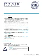
charging from 12 V dc Vehicle Accessory Socket

A  lead  suitable  for  charging  Pyxis  from  a  vehicle  is  available  from  the 
manufacturer as an accessory. Refer to instructions provided with the lead for 
detailed instructions.

Ensure that the unit is safely secured to the vehicle if 
charging while driving.

Charging Pyxis while the engine is not running can flatten the 
vehicle’s battery.

3.2.3.1 Connecting

1. 

Start the vehicle’s engine.

2. 

Connect the large connector to the front panel of Pyxis.

3. 

Connect the small connector to the vehicle’s accessory socket.

3.2.3.2 Disconnecting

1. 

Disconnect the small connector from the vehicle’s accessory socket.

2. 

Disconnect the large connector from the front panel of Pyxis.

3. 

Stop the vehicle’s engine.

Summary of Contents for PYX/400/250

Page 1: ...se with the following models PYX 800 250 PYX 800 250 S PYX 800 250 1 PYX 800 250 1 S PYX 400 250 PYX 400 250 S PYX 400 250 1 PYX 400 250 1 S PYX BEM 110 User manual v3 2 www fireflysolar net Pyxis Power Pack ...

Page 2: ... Time 8 2 3 The Pyxis Control Panel 9 2 4 Connecting Pyxis 10 2 4 1 Earth attachment Installing the Earth Rod 10 2 4 2 Connect The Input 11 2 4 3 Connect The Output 11 3 General Operation 12 3 1 Turning The Power On 12 3 1 1 Monitoring the Power 12 3 1 2 Turning Off Pyxis 12 3 1 3 Disconnecting Pyxis 13 3 2 Charging Methods 13 3 2 1 Charging with AC DC Mains Battery Charger 13 3 2 2 Connecting the...

Page 3: ...o Pyxis 22 4 1 3 Connecting Additional Battery Extender Modules to Pyxis 22 4 1 4 Charging Battery Extender Modules 22 5 Technical Information 23 5 1 Pyxis Run Times 24 5 2 Warnings 24 5 2 1 Safety Notice Regarding The Units Batteries 24 Figures Fig 1 Control Panel 9 Fig 2 Earth Rod 10 Fig 3 AC Output Protection 12 Fig 4 Main Isolator 12 Fig 5 Inverter On Off Switch 12 Fig 6 Battery Condition Indi...

Page 4: ... manual is to introduce you to Pyxis and provide you with a guide to its safe installation and operation This manual describes how your Pyxis works will help you with fault finding and examines what the key components are doing and why 1 2 Conventions Throughout this user manual the following symbols are used WARNING This symbol warns of the presence of a dangerous voltage which could cause harm t...

Page 5: ...ortant part of Pyxis It must be kept available to all operators and kept close to the unit so that it can be referred to at any time WARNING When the unit is operating it generates potentially lethal voltages Work must only be performed on the unit by the manufacturer or a qualified service engineer approved by the manufacturer All items connected to the unit including distribution cables and boxe...

Page 6: ... 2004 EN61000 4 4 2004 EN61000 4 8 1993 EN61000 4 5 1995 EN61000 4 2 1995 1 5 Disposal Recycling Pyxis comprises of components that must disposed of responsibly For the sake of the environment many of the components within the unit can be recycled or reused Firefly will ensure the safe decommissioning and recycling of the unit at no charge if the unit is returned to the manufacturer Otherwise plea...

Page 7: ... meet the needs of environmentally concerned individuals and organisations internationally that are looking to reduce their carbon emissions caused by the use of fossil fuels and diesel powered equipment The unique range of renewable technology solutions produce zero emissions are truly silent running and eliminate the need for fuel The systems are manufactured in the UK under an ISO 9001 2008 app...

Page 8: ...charge of the battery bank 2 1 2 Lifting Pyxis is designed to be easily liftable without the need for lifting gear or machinery It is recommended that either Pyxis or the Battery Extender are lifted from the in built handles by two persons 2 1 3 Positioning 1 The unit must be positioned upright on a flat solid surface Ensure that the unit is not at risk from being submersed in water 2 Position the...

Page 9: ...Off Switch 5 Solar Array Inputs 6 Solar Array Indicator 7 Main Isolator 8 Battery Extender Module 12 V DC Charging 9 Earth Point 10 AC Output Indicator 11 230 V AC Output Fig 1 Control Panel 2 3 The Pyxis Control Panel Solar Isolator Solar Array Inputs and Solar Array Indicator are only available on units with the solar prep option ...

Page 10: ...s available from the manufacturer as an accessory 2 4 1 Earth attachment Installing the Earth Rod 1 The Earth Point of Pyxis is located on the front panel Fig 1 Control Panel on page 9 2 Find a suitable place to drive the earth rod Fig 2 Earth Rod into the ground The earth rod should be driven down at least half way into the ground using a mallet and placed as near to the unit as possible 3 Check ...

Page 11: ... 9 is switched Off 2 Plug electrical consumers in to the 230 or 110 V AC Out socket on the control panel Fig 1 Control Panel on page 9 using a 16 A CEE Form industrial plug WARNING Care must be taken to ensure that the correct connections are made to avoid the risk of electrocution or possible damage to the unit s internal components The protection provided by the unit may be impaired If the unit ...

Page 12: ...Control Panel on page 9 will illuminate to indicate that the unit is now on and ready to supply power to connected consumers 3 1 1 Monitoring the Power An analogue battery condition indicator is provided see Fig 6 Battery Condition Indicator on page 13 to give an overview of the internal battery s State Of Charge For maximum life of the batteries it is recommended that the system is not allowed to...

Page 13: ...th Point wing nut 8 Replace the washer and wing nut onto the Earth Point bolt Fig 1 Control Panel on page 9 3 2 Charging Methods Pyxis can be charged using a number of methods AC DC Mains Charger Vehicle Accessory Socket Solar Fold Array or Kinectrics PedGen 3 2 1 Charging with AC DC Mains Battery Charger The unit connected Battery Extender Modules and individual Battery Extender Modules can be ch...

Page 14: ...et on the front panel Fig 1 Control Panel on page 9 2 Follow the operation instructions included with the charger 3 Battery charging and State Of Charge monitoring is handled by the battery charger 4 Disconnect the external battery charger when it indicates that the battery is fully charged 3 2 2 1 Charging the Pyxis while connected to one or more Battery Extender Modules The included battery char...

Page 15: ...om the manufacturer as an accessory Refer to instructions provided with the lead for detailed instructions Ensure that the unit is safely secured to the vehicle if charging while driving Charging Pyxis while the engine is not running can flatten the vehicle s battery 3 2 3 1 Connecting 1 Start the vehicle s engine 2 Connect the large connector to the front panel of Pyxis 3 Connect the small connec...

Page 16: ...t easily and possible electrocution 6 Once all connections are safely made switch on the solar isolator switch on the control panel Fig 1 Control Panel on page 9 7 Ensure that the main isolator is switched on Pyxis and connected Battery Extender Modules will only charge from the solar input with the main isolator in the on position 8 The Battery Condition Indicator will move to the maximum positio...

Page 17: ...p information the equipment can be connected 4 Ensure that the Main Isolator switch Fig 1 Control Panel on page 9 is in the Off position 5 Connect the lead to the Battery Extender Module 12 V DC Charging connector on the Pyxis control panel Fig 1 Control Panel on page 9 6 Switch on the unit using the Main Isolator switch Fig 1 Control Panel on page 9 3 2 5 2 Disconnecting 1 Switch off the unit usi...

Page 18: ...y debris and dust should be removed and or cleaned from the filter by brushing or light vacuuming 4 If the filter element becomes damaged or is soiled beyond cleaning replacement is necessary Contact the manufacturer for replacement filter elements Operating the unit without a correctly fitted Dust Filter may allow the ingress of dust particles and potentially damage internal components 3 3 2 4 Re...

Page 19: ...d that the unit should be tested annually for electrical safety by a qualified electrician Local regulations may require more frequent testing Please refer to local regulations for further details WARNING If Pyxis fails the relevant tests do not use or open the unit It must only be opened by a qualified service engineer It is recommended that a full service is performed every two years in order to...

Page 20: ...nnected consumers are drawing too much power for the rated output of the unit Refer to the maximum output rating on the unit s rating plate and reduce the total power draw accordingly When switching the Inverter on with the Inverter On Off switch its red LED illuminates but the green AC Output Indicator does not illuminate The AC Output Protection Switch is in the off position Switch the AC Output...

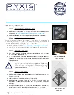
Page 21: ...xtended run times for Pyxis 4 1 1 Stacking Interlocking corners are featured on both Pyxis and the Battery Extender Modules allowing up to three Battery Extender Modules to be safely stacked with Pyxis Fig 10 Pyxis with Battery Extender Module on page 21 Do not stack more than one Pyxis and three Battery Extender Modules four units in total Fig 10 Pyxis with Battery Extender Module ...

Page 22: ...ding power to consumers This allows hot swapping of Battery Extender Modules 4 1 3 Connecting Additional Battery Extender Modules to Pyxis 1 A link lead is supplied with each Battery Extender Module 2 Connect one end of the interconnecting cable to the Battery Extension 12V DC Charging connector on Pyxis 3 Connect the other end to one of the Battery Extender Module 12 V DC In Out connectors it doe...

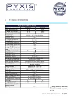
Page 23: ...Power Output Connection 1 x 16 A 230 V SP CEE Form Socket Solar Power Input Connection Multi Contact 30 A MC3 DC Input Output Connection 1 x 120 A 12 V DC Grey SB120 Anderson Inverter Protection Short Circuit Inverse Polarity Overload Overheat Low Battery Circuit Protection RCBO 230 V AC 6 A 110 V AC 10 A Earth Fault Protection RCBO 230 V AC 6 A 110 V AC 10 A Battery Monitoring Battery Condition I...

Page 24: ...ION Do not dispose of batteries in a fire The batteries may explode CAUTION Do not open or mutilate batteries Released electrolyte is harmful to the skin and eyes It may be toxic Pyxis Run Times No External Charge Model PYX 400 250 PYX 400 250 Battery Extender PYX 400 250 2 x Battery Extenders PYX 800 250 PYX 800 250 Battery Extender PYX 800 250 2 x Battery Extenders Run Time at 100 W Output e g P...

Page 25: ...to be added or removed without interrupting the output of the Pyxis Power Pack Power Storage Extender 12 V DC Vehicle Accessory Socket Fold Array 360 Wp 12V FOL 360 4 12 16 A Plug to 13 A Adapter in line 4 Way 230 V 5m 16 A Extension Cable 110 V 230 V 10m 16 A Extension Cable 110 V 230 V Earth Rod with Clamp 1m Earth Cable 0 5 Interconnect cable 120 A 12 V DC Grey SB120 Anderson for extender 15 A ...

Reviews: