background image

13 

INSTALLATION


BEFORE INSTALLING

 the Firecom 5000D Series Intercoms, make sure you have read and understood the entire 

installation procedure. You should also read the sections on Pre-Installation (page 7) and System Orientation (pages 3-5). 

If any item in the Installation Procedure is not understood, or if you have any questions which are not addressed in this 

manual, contact your local Firecom Dealer for more information BEFORE you proceed with the installation. 

MOUNTING THE INTERCOM: 


Using the mounting bracket as a template, mark the location of the mounting holes.  


Using a 3/16" drill bit, drill 2 holes for the #8 sheet metal screws (supplied).  


IMPORTANT: 

Be sure the area behind the panel you are drilling into is free of wires or other obstructions that 

could be damaged while drilling the holes 


Install the mounting bracket with the sheet metal screws (Figure 8). 


Remove the 4 screws (2 on each side) closest to the rear of the Intercom unit and mount the Intercom on the 

mounting bracket with the 4 screws. 


IMPORTANT: 


DO NOT completely tighten the Intercom mounting hardware until the entire installation is 

complete. 

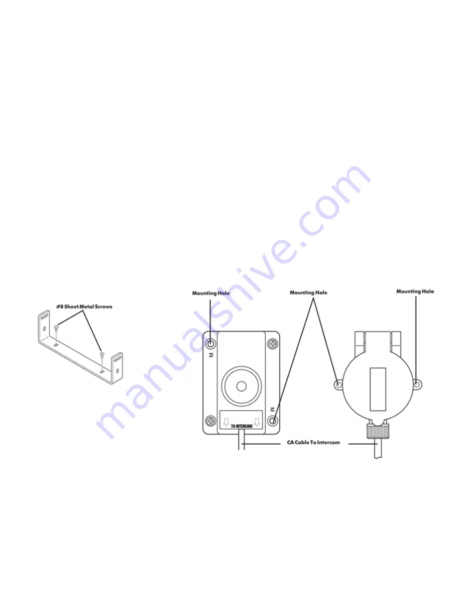
MOUNTING THE HEADSET MODULES: 


Using the Headset Module as a template (Figure 9), mark the location of the mounting holes.  The holes in the 

HM-10 used for mounting the module are marked with a letter "M". 


Using a 5/32" drill bit, drill 2 holes for the #6 sheet metal screws (supplied). 


IMPORTANT: Be sure the area behind the panel you are drilling into is free of wires or other obstructions that 

could be damaged while drilling the holes. 


Position the Headset Module and secure with the provided sheet metal screws. 


FIGURE 8: The Mounting Bracket  


Figure 9:  Headset Modules 


Summary of Contents for 5000D Series

Page 1: ...1 5000D Series Digital Intercoms 5100D 5200D 5300D 5400D Series Digital Intercoms Remote Intercoms Installation Operation Manual...

Page 2: ...2...

Page 3: ...EAR PANEL 8 PRE INSTALLATION 9 INSTALLATION 13 SYSTEM TEST 18 INTERCOM OPERATION 19 PROGRAMMING INPUT AND OUTPUT DEVICE GAIN 19 MODULAR PLUG INSTALLATION 23 TROUBLESHOOTING 24 ADVANCED TROUBLE SHOOTIN...

Page 4: ...erproof remote Intercom head for outdoor installations Each crew member will hear all radio traffic and be able to communicate over the Intercom Crew members wearing Radio Transmit headsets may transm...

Page 5: ...tact your local Firecom Dealer for more information regarding an Interface Cable specific to your radio POWER CABLE ASSEMBLY Provides the power connections for the 5000D Series Intercom Unit The power...

Page 6: ...microphone volume and sensitivity for various ambient background noise levels RADIO INTERFACE PORT A 9 pin D sub jack on the rear of the Intercom RADIO INTERFACE CABLE The cable which plugs into the R...

Page 7: ...H LEVEL DOWN BUTTONS 10 red LED s which indicate the master volume level setting There are 3 volume changes between lights RADIO SELECT LED BUTTONS Green LED o The green LED indicates which radio is t...

Page 8: ...he Power Cable Assembly is plugged in to interface the 5000D Series Intercom to the vehicle s power supply MODULAR JACKS The modular jacks are the connection points for the CA Cables leading from the...

Page 9: ...r of the Intercom unit for service and installation The Digital Intercom should be placed where it will be easy to route all the CA Cables from the Headset Modules The Digital Intercom should be place...

Page 10: ...a method used to increase the number of headset positions available or a method of reducing the number of cable runs and the length of the cable runs Daisy Chaining the Headset modules is easy to acc...

Page 11: ...ovide Intercom and radio communication to the headset positions REMOTE MODULAR JACKS On the rear of the Intercom there is 1 modular jack under REMOTE Figure 4 This jack is for connecting CA Cables for...

Page 12: ...d radio technician Contact your local Firecom Dealer for more information regarding the availability of an interface cable for your radio If a radio specific cable is not available for a particular ra...

Page 13: ...obstructions that could be damaged while drilling the holes Install the mounting bracket with the sheet metal screws Figure 8 Remove the 4 screws 2 on each side closest to the rear of the Intercom uni...

Page 14: ...adset Module to the Intercom it MUST be inserted into the Modular Jack on the same side of the HM 10 as the Firecom label If the CA Cable is part of a daisy chain you will need to remove the plastic t...

Page 15: ...om pin 1 to the vehicle s negative ground or use the supplied self tapping screw and star washers as shown in Figure 14 FIGURE 13 Modular Jacks IMPORTANT Firecom recommends connecting the Intercom pow...

Page 16: ...ocal Firecom Dealer Plug the 9 Pin plug on the end of the MR 0X Mobile Radio Interface Cable into the desired Radio Interface Jack on the rear of the Intercom Figure 15 IMPORTANT Tighten the 2 screws...

Page 17: ...heet metal screws 4 making sure the cable is not pinched Recommended torque 10 in lbs 5 Determine the correct length for the CA cable and cut cable to correct length Mounting with Bracket part number...

Page 18: ...ATION IMPORTANT The next 4 steps are for Radio Transmit Headsets only These are the BEHIND THE HEAD 51 Series models and OVER THE HEAD 51 Series models and have a red PTT on the ear dome 1 Put on a Ra...

Page 19: ...just the Receive Audio Adjustment or the radio s volume control INTERCOM ADJUSTMENTS AND OPERATIONS For the Radio Aux and Cell connections to the Intercom the user can adjust input gain and output gai...

Page 20: ...h up and Squelch down buttons for 5 seconds FIGURE 19 2 Once squelch control mode has been successfully entered the squelch level LEDs will flash 3 You will also note that the lowest volume LED is fla...

Page 21: ...is the transmit radio This radio will be used when any user presses the PTT button on their headset To select another radio as the transmit radio simply press the button that corresponds to that radio...

Page 22: ...too much traffic and is distracting it can be deactivated by pressing and holding the Aux button for 3 seconds This will turn off the green LED indicating that no audio from that Aux Port will be hea...

Page 23: ...ation should expose approximately 3 16 of wire Figure 22 6 Push a RJ 12 Modular Plug into the plug holder on the crimping tool labeled D in Figure 21 until the release tab on the plug locks into posit...

Page 24: ...Advanced Troubleshooting procedures on pages 24 25 ALTERNATOR WHINE OTHER DISTRACTING NOISES Because of the level of ambient noise present with the apparatus motor running alternator whine and other...

Page 25: ...e the mic for Intercom communication The mic will remain active until the Yellow PTT is pressed again Plug the headset into another good headset configuration If the headset fails to perform properly...

Page 26: ...ain Check the radio volume Make sure it is not turned all the way down If there is no audio from the radio s speaker o Disconnect the Radio Interface Cable from the radio If there is audio from the ra...

Page 27: ...or unplugging a headset when not in use Unplug the headset locations one at a time from the rear of the Intercom Unit until the squeal stops Check the headset configuration for faulty connections or c...

Page 28: ...28 WIRING DIAGRAM SCHEMATICS...

Page 29: ...29 Wiring Diagram Schematics Headset Module Wiring Remote Head Wiring...

Page 30: ...hms Output Voltage 370 mV 114 SPL re 0002 microbar Frequency Response Optimized for speech clarity and noise reduction Max Amb Noise Level 125 dB SPL re 0002 microbar Weight 0 2 oz INTERCOM Size 6 6 L...

Page 31: ...0676 00 HANDHELD RADIO INTERFACE Works with all Firecom headsets Contact your Firecom Dealer for specific information regarding your particular handheld radios MIC MUFFS DOZEN Replacement mic muffs w...

Page 32: ...ency energy and if not installed and used in accordance with the instruction manual may cause harmful interference to radio communications Operation of this equipment in a residential area is likely t...

Page 33: ...or an Firecom Authorized Service Provider f to a product or part that has been modified without the written permission of Firecom g if any Firecom serial number has been removed or defaced 7 This war...

Page 34: ...34...

Page 35: ...35...

Page 36: ...firecom com Copyright 2019 Sonetics Corporation All rights reserved The information in this document is subject to change without notice No part of this document may be copied or reproduced in any fo...

Reviews: