


FIRECLASS Prescient III
6.3 Commissioning Procedure
Application, Installation & Commissioning Doc. version 2
45
5
Remove the control panel chassis (complete with
power supply & control board) from its fixings by
undoing the screws located on the chassis. The bot-
tom left & right screws need to be removed com-
pletely, the top left & right screws can just be slack-
ened. The chassis can then be pushed upwards and
removed. Rest the chassis in the bottom of the
enclosure and disconnect the internal mains cables
from the terminal block at the top-right of the
enclosure.
6
Remove the chassis and place the complete chassis
unit safely to one side.
Do not remove the con-
trol board or the power supply unit from the
chassis.
7
Place the empty enclosure against the wall, mark
and fix using the single fixing hole in the upper sec-
tion of the enclosure. Level the enclosure and com-
plete the fixing operation using the remaining two
fixing holes in the lower section of the enclosure.
The fixing holes are suitable for 5 mm diam-
eter screws (imperial size 10). Use stainless
steel or plated screws.
8
Gland the installation wiring into the enclosure using
the cable entry knockouts provided at the top of the
enclosure.
9
When all installation wiring is complete, check all the
wiring to ensure that it is free from short circuits,
open circuits, earth faults, crossed connections etc.
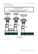
10 Connect the end of line capacitor across the termi-
nals of the last device in each of the three zone wir-
ing runs. The end of line capacitors are provided in
the small plastic bag supplied with the panel.
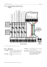
11 Check that any Manual Call Points on the aux. zone
are fitted with an activation resistor (in the range
100 Ω to 680 Ω).
12 Connect a 10 kΩ EOL resistor across the terminals
of the last device on the Manual Release zone.
13 Connect a 10 kΩ EOL resistor across the terminals
of the last device in each of the alarm wiring runs.
14 Connect a 10 kΩ EOL resistor across the terminals
of the last device in each of the solenoid wiring runs.
If you are using the C1565 monitoring and suppres-
sion board instead of the end of line resistor, then
note that only one board can be used on each circuit.
15 Connect a 10 kΩ EOL resistor across the terminals
of the last device for any additional monitored input
or output circuits being used.
16 Place the chassis in the bottom of the enclosure and
Re-connect the internal mains cables to the mains
terminal block. Ensure that the Earth lead to the
Earth Bar is connected to the Mains Terminal block.
17 Re-connect the Earth lead to the chassis and refit the
chassis on the four mounting screws. Reconnect
the display ribbon cable to the motherboard.
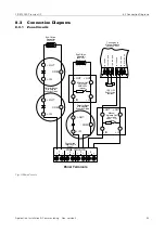
18 Connect 230 V AC mains to the mains terminal block
provided inside the enclosure, ensuring that the
mains supply is isolated at the source. The mains
cable must be secured inside the enclosure using a
Cable Tie (see Fig. 6 – Power Supply Connection
Details).
6.3
Commissioning Procedure
In order to avoid accidental operation of the solenoid
valves during commissioning the solenoid valves should
remain disconnected during the commissioning pro-
cess. A suitable load resistor (typically 47 Ω, 20 W, pro-
viding a 0.6 A load, check manufacturer’s datasheet for
actual current or coil resistance) should be connected in
place of the solenoid to simulate the presence of the
solenoid coils. The solenoid coils should be connected
only at the end of the commissioning process.
The commissioning engineer should also be aware of
any additional equipment connected to the panel and
the consequences of the operation of that equipment
during the commissioning process.
Make sure that the
BEDIENING
Keyswitch is in the
AAN
position before operating any of the buttons on the dis-
play board.
ALL internal DIL switches should be in the OFF position
at the start of the commissioning process detailed
below.
1
Turn ON the mains supply to the panel, and observe
that the control panel reacts as follows:
NOTICE: Disconnection Device
An appropriate lockable double pole dis-
connect device shall be provided as part of
the building installation. This device must
have a minimum contact gap of 3 mm.
The mains supply should be protected by a
5 A fuse.
Use only mains cable compliant to
BS6004, BS6500, or equivalent, within the
following limits shown in Table 15.
Cable
Diameter
Conductor
Diameter
Minimum
Dimensions
4.0 mm
1.0 mm
(0.8 mm
2
)
Maximum
Dimensions
8.0 mm
2.25 mm
(4.0 mm
2
)
Table 15: Mains Cable Compliant Limits
CAUTION:
DO NOT TURN ON THE MAINS SUPPLY
TO THE CONTROL PANEL AT THIS
STAGE.
Do not connect any field wiring at this
time.


