

Electromagnetic Compatibility
The FC420CP complies with the following:
Ø
product family standard EN50130-4 in respect of Conducted
Disturbances, Radiated Immunity, Electrostatic Discharge,
Fast Transients and Slow High Energy;
Ø
EN61000-6-3 for emissions.
INTRODUCTION
FC420CP Addressable Break Glass Callpoint is designed to mon-
itor and signal the condition of a switch contact that is operated by
activating the break glass element. The glass element may be re-
placed with a deformable plastic element which allows the
FC420CP device to be reset, using the key supplied, after alarm
activation. The type of alarm generated by the callpoint is config-
ured in FireClass Console.The FC420CP call point meets the re-
quirements of EN54 Pt.11. The FC420CP is fitted to a standard
surface mount plastic backbox, standard single gang metal plaster
box (35 mm for flush mounting) or standard single gang metal
plaster box (25 mm) with backbox.
+
Note: plaster boxes should have 20 mm knockouts.
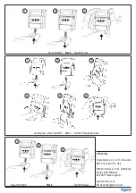
ADDRESS PROGRAMMING
The FC420CP has a default factory set address of 255, this must be
set to the loop address of the device using FC490ST Loop Service
Tool. The FC420CP is programmed with its address using the pro-
gramming port at the rear of the callpoint before mounting to the
backbox as shown in Fig. 3.
+
Note: once the address has been programmed take note of the
device location and address number to include on site drawings.
MOUNTING
Mount to a standard break glass callpoint housing, or standard
single gang metal plaster box (35 mm for flush mounting or 25
mm) with standard break glass callpoint housing.
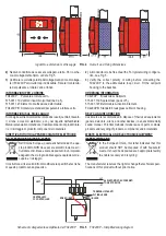
CABLING
Cables are to be selected in accordance with the FireClass design
document .Cabling should be connected as shown in Fig. 5 ensur-
ing correct polarity. Couplers are to be used with MICC cable.
WIRING NOTES
1)
There are no user-required settings (such as switches or head-
ers) on the FC420CP.
Compatibilità Elettromagnetica
Il modulo FC420CP è conforme a quanto segue:
Ø
famiglia di prodotto standard EN50130-4 rispetto alle Perturba-
zioni Dirette, Immunità Irradiata, Scarica Elettrostatica, Transi-
torie Rapide e Alta Energia Lenta;
Ø
EN 61000-6-3 per le emissioni.
INTRODUZIONE
Il pulsante a rottura vetro indirizzabile FC420CP è progettato per monito-
rare e segnalare lo stato di un interruttore che è attivato dalla rottura del
vetrino. È possibile sostituire il vetrino con un elemento plastico deforma-
bile che permette, dopo l'attivazione dell'allarme, il ripristino del pulsante
FC420CP tramite la chiave in dotazione. Il tipo di allarme generato dal
pulsante è configurabile con FireClass Console. Il pulsante FC420CP
soddisfa i requisiti EN54 Pt.11. Il pulsante FC420CP può essere fissato
ad una scatola standard per il montaggio a parete di materiale plastico,
ad una scatola americana single-gang da incasso, di metallo (da 35 mm
per il montaggio ad incasso) o ad una scatola americana single-gang da
incasso, di metallo, da 25 mm, tramite una scatola standard.
+
Le scatole da incasso devono avere fori a sfondamento da 20 mm.
PROGRAMMAZIONE
L'indirizzo di fabbrica del FC420CP è 255, questo deve essere impo-
stato all'indirizzo di loop del dispositivo tramite lo strumento per la pro-
grammazione dei dispositivi indirizzabili FC490ST. L'indirizzo del
FC420CP può essere programmato usando la porta di programma-
zione posteriore prima del montaggio della scatola (vedere Fig. 3).
+
Nota: una volta programmato l'indirizzo, annotare la posizione del
dispositivo e l'indirizzo, per segnarlo sul progetto dell'impianto.
MONTAGGIO
Montare su un contenitore standard per pulsanti a rottura vetro, o
su una scatola americana single-gang da incasso, di metallo da
35 mm, per il montaggio ad incasso, o da 25 mm con un contenito-
re standard per pulsanti a rottura vetro.
COLLEGAMENTI
I cavi devono essere selezionati in conformità con il documento di pro-
gettazione del sistema FireClass. I collegamenti devono essere effet-
tuati come mostrato in Fig. 5 rispettando la corretta polarità. Usare degli
accoppiatori con cavi MICC (cavi in rame con isolamento minerale).
NOTE PER IL COLLEGAMENTO
1)
Sul FC420CP non ci sono regolazioni da effettuare (interruttori
o altro).
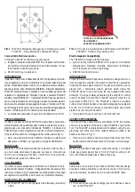
FC420CP–Dimensioni fissaggio per il montaggio a parete
FIG. 2
FC420CP – Fixing Dimensions Surface Mounting
PORTA PER LA PROGRAMMAZIONE
DELL’INDIRIZZO
ADDRESS PROGRAMMING PORT
Porta per la programmazione dell'indirizzo del FC420CP
FIG. 3
FC420CP – Address Programming Port


