FireBird Enviromax Kitchen C12 Technical Manual Download Page 14

6

12

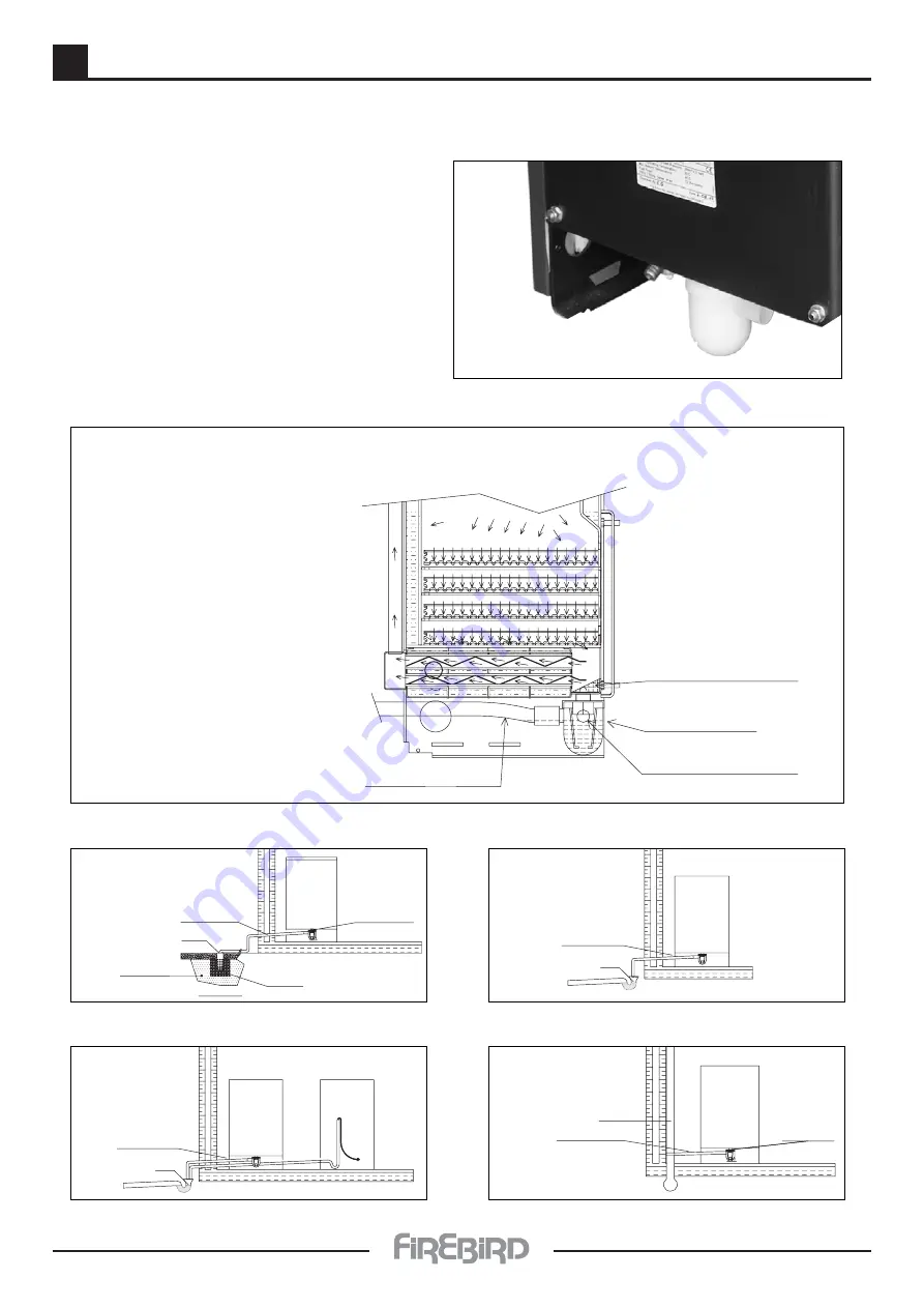
6.3 INSTALLATION - CONDENSATE DISPOSAL

CONDENSATE DISPOSAL

METHOD 1

CONDENSATE TRAP

IMPORTANT

Always prime condensate

trap with water.

Figure 1

Boiler

Sealed

Condensate Drain

Condensate Drain

Trap

Lime Stone
Chippings

Free Draining Soil

Soak Away

F

igur

e 1

Boiler

Condensate Drain

Washing
Machine

Gully

Waste

Pipe

 Trap

F

igur

e 2

Boiler

Condensate Drain

Gully

 Trap

F

igur

e 3

Boiler

Condensate drain

Stack

Trap

Discharge pipe

Condensate drain must have
a minimum diameter of 22mm
and it must be supported with
a 2.5˚ (1:100) fall from boiler.

F

igur

e 4

Condensate drain baffle

Condensate drain float

Condensate baffle and condensate trap

Condensate trap

Condensate hose

Before switching on your 
Firebird condensing oil boiler 
check that:

(1)   The float  & condensate drain
 

baffle are in place.

(2)   That the condensate trap
 is 

primed.

(3)   The condensate discharge
 

pipe is a corrosion

 resistant 

pipe.

The condensate trap is located
at the base of the boiler.

Summary of Contents for Enviromax Kitchen C12

Page 1: ...AL MANUAL INCLUDES END USER INSTRUCTIONS INSTALLER GUIDE COMMISSIONING SERVICING PARTS ENVIROMAX CONDENSING RANGE This manual must remain with the end user on completion of installation TECHNICAL MANU...

Page 2: ......

Page 3: ...ating Circuit 14 6 5 Flue Regulations 17 6 6 Ventilation Combustion Air Requirements 21 6 7 Flue Assembly 25 6 8 Wiring 26 6 8 1 System Boiler 26 6 8 2 Kitchen Basic Commercial Utility Boilers 27 6 8...

Page 4: ...of experience Firebird domestic or commercial condensing boilers are highly efficient and are all independently certified to SEDBUK Band A They use less fuel and have lower running costs than non con...

Page 5: ...Min System Pressure Cold 0 5 bar Preset Pressure Relief Valve 3 bar MAINS WATER SUPPLY PRESSURE Min 1 bar Max 10 bar for user comfort we recommend pressure at tap to be between 2 and 5 bar Limescale...

Page 6: ...R SUPPLY PRESSURE Min 1 bar Max 10 bar for user comfort we recommend pressure at tap to be between 2 and 5 bar Limescale excess When over 150 200 ppm fit appropriate scale reducer WATER SIDE RESISTANC...

Page 7: ...e HEATING SYSTEM SEALED Fit in accordance with BS 7074 Part 1 BS 5449 OFTEC standards and all other relevant legislation Max Operating Pressure 2 5 bar Max System Pressure Cold 1 5 bar Min System Pres...

Page 8: ...em is installed to comply with manufacturers instructions and AS1691 1985 Domestic Oil fired Appliances Installation Please ensure that the appliance is bolted to the floor for seismic restraint Fireb...

Page 9: ...nly likely to arise following harsh abrasion Suitable personal protective equipment should be worn where appropriate Generally normal handling and use will not give discomfort Follow good hygiene prac...

Page 10: ...call for heat Set the boiler thermostat to the required temperature see Figure 1 on next page The boiler thermostat controls the boiler operation by automatically maintaining the required boiler wate...

Page 11: ...il nozzle Before attempting to restart the boiler the front panel and the burner cover should be removed and a visual check made for any obvious problems such as oil leaks loose connections etc ENSURE...

Page 12: ...important points before commencing installation Failure to do so will invalidate warranty INSTALLATION COMMISSIONING Boilers must be installed commissioned and serviced by qualified and experienced p...

Page 13: ...s through a bedroom it is capable of transmitting noise 3 Low level balanced flue terminals can produce exhaust noise on the outside terminal and this should be considered when siting near adjacent pr...

Page 14: ...ure 3 Boiler Condensate drain Stack Trap Discharge pipe Condensate drain must have a minimum diameter of 22mm and it must be supported with a 2 5 1 100 fall from boiler Figure 4 Condensate drain baffl...

Page 15: ...ld be plastic and minimum diameter of 22mm Copper or steel cannot be used A fall from the boiler of 1 100 minimum As few bends as possible to reduce the risk of trapping condensate CONDENSATE PIPEWORK...

Page 16: ...sure gauge should enter this red zone showing a final system design pressure of more than 21 2 bar it is likely that a Total system water content is greater than that calculated and if additional expa...

Page 17: ...lling may be made with a feed and make up cistern connected through a double check valve and stop valve assembly to the return side of the heating system as close to the boiler as is practical This ci...

Page 18: ...opriate boiler and system valves are open With water supply turned off thoroughly flush out boiler and system to remove all foreign matter before allowing boiler and pumps to operate If in doubt drain...

Page 19: ...FOR ANY BUILDING REGULATIONS AMENDMENTS WHICH MAY HAVE BEEN ISSUED AFTER THE PUBLICATION OF THIS MANUAL A A C B C A Horizontal from opening airbrick opening window etc B From an internal or external c...

Page 20: ...balcony without protection 1000 E From vertical sanitary pipe work 300 F From an internal or external corner or surface or boundary alongside the terminal 300 G Above ground or balcony level 300 H Fro...

Page 21: ...en tested to BS EN 303 1 5 Terminating positions must be at least 1 8m distant from an oil storage tank unless a wall with at least 30 minutes fire resistance and extending 300mm higher and wider than...

Page 22: ...ired to ventilate and to avoid overheating in the boiler area OPEN FLUE BOILER IN ROOM BOILER COMPARTMENT VENTILATED FROM OUTSIDE BOILER COMPARTMENT VENTILATED FROM ADJOINING ROOM 5 5cm2 kW 5 5cm2 kW...

Page 23: ...verall length must take into account bends where 45 bend 0 5 m length and 90 bend 1 m length INSTALLATION INSTRUCTIONS SUPPLIED WITH ALL FLUE KITS Elbows 45 90 Adjustable extensions 305 420mm 555 920m...

Page 24: ...flue system which is unsuitable is used it will invalidate the warranty Because of the high operating efficiencies of the Firebird condensing boilers and low flue gas temperatures it is necessary to p...

Page 25: ...isperse causing the photocell to become dirty ITEMS TO BE CHECKED IN ALL CASES WHERE A BOILER IS OF CONCERN There are four checks that must always be made where a photocell has stopped a burner 1 Ensu...

Page 26: ...aptor Condensing boiler Condensing boiler Boiler C26 C35 C44 C58 C73 Diameter 80mm 100mm 100mm 125mm 150mm FLUE SIZE NOTE All brick chimney constructions must comply with current building regulations...

Page 27: ...6 25 6 7 INSTALLATION FLUE ASSEMBLY SLIMLINE SYSTEMPAC...

Page 28: ...and controls require 230V 50Hz mains electric supply protected with a 5A fuse The warranty on this product will be rendered void if damaged by power from a stand by electricity supply i e generator T...

Page 29: ...ntrols require 230V 50Hz mains electric supply protected with a 5A fuse The warranty on this product will be rendered void if damaged by power from a stand by electricity supply i e generator This app...

Page 30: ...t thermostat 5 C 14 ELECTRICAL SUPPLY The boiler and controls require 230V 50Hz mains electric supply protected with a 5A fuse The warranty on this product will be rendered void if damaged by power fr...

Page 31: ...between a flue exit and fire barrier see page 21 flue clearances Diesel storage tanks should not be sited within 1 8m of boiler flue outlets Do not allow household waste or hot ashes container in vic...

Page 32: ...Single pipe Diesel supply with deaeration device eg deaerator Bottom of diesel tank below or level with burner Adapted from OFTEC drawing Filter Shut off valve Fire valve Deaeration device Optional p...

Page 33: ...anent power supply available via a fused spur with a 5amp fuse Oil supply The burner is set for Diesel 35 Second Gas Oil Check that there is a good quality filter on the line with an isolating valve T...

Page 34: ...of burner Ensure flue gas is over 50 C when setting CO2 Allow the boiler to run for a period of time before fine tuning to the Firebird settings This fine tuning should be done with the boiler in the...

Page 35: ...diesel leaks Draw off any accumulated water and sludge from the tank by opening the drain valve Turn off the diesel supply and remove the filter bowl then wash the element clean with diesel Fit a new...

Page 36: ...for electrodes Air Box 1 Air Box 2 T1 Part No 7137 T5 Part No 7140 T3 Part No 7139 Riello RDB 2 2 Range Burner Settings Variations in nozzle throughput flue type draught oil viscosity etc may give re...

Page 37: ...e and anti clockwise to decrease until the numbers line up with the edge of the blast tube A These settings are a guide for the commissioning engineer and may give varying results in different site lo...

Page 38: ...o allow working with one pipe TWO PIPE In order to obtain two pipe working it is necessary to unscrew the return plug 2 screw in the by pass screw 3 and then screw in return oil line 2 See fig 4 In th...

Page 39: ...9 37 9 4 BURNER FAULT FINDING T Repair or Replace Oil Pump r No Troubleshooting Guide for Riello RDB Burner Fault Finding Logic For Control Box Type 5352 SE LD RDB Series Oil Burners...

Page 40: ...LER 53 52 46 51 47 45 50 48 49 48 4 3 5 9 8 7 6 35 42 1 2 14 12 10 11 13 34 18 24 26 25 22 23 20 32 19 21 30 29 28 31 15 16 17 33 26 27 36 37 38 39 40 41 44 43 49 42 54 51 16 49 38 39 45 50 59 62 53 5...

Page 41: ...28 Casing Top 111375 111375 111375 111793 29 Casing Flue Blank 111388 111388 111388 111586 30 Casing Flue Trim 111397 111397 111397 111587 31 Casing Top Insulation 111794 111794 111794 111789 111791 3...

Page 42: ...10 40 10 2 PARTS BAFFLES KITCHEN BASIC COMMERCIAL UTILITY BOILERS 4 3 5 9 8 7 6 25 16 1 2 14 12 10 11 13 36 24 18 19 28 27 26 21 17 15 32 34 33 30 29 20 31 22 23 37 38 35...

Page 43: ...Lagging Jacket 113029 110917 110917 111653 111653 111438 112633 18 Casing Left Panel 111377A 111377A 111377A 111761 111761 111580 213108 19 Casing Right Panel 111377B 111377B 111377B 111766 111766 11...

Page 44: ...FLES SLIMLINE SYSTEMPAC BOILER 12 2 22 24 23 35 21 3 4 5 6 7 8 9 10 11 15 16 13 42 43 44 45 1 26 31 19 26 30 46 25 28 34 37 36 38 17 18 20 14 41 40 39 27 32 33 29 52 53 54 51 49 48 50 51 47 55 Only fo...

Page 45: ...23 Casing Front 211604 211604 24 Casing Front Lagging 112010C 112010C 25 Boiler Lagging 110917 110917 26 Casing Side Lagging 112010D 112010D 27 Casing Top Lagging 112010E 112010E 28 Casing Flue Outlet...

Page 46: ...0 3 L L E C E P 2 1 7 5 6 2 0 0 3 T E K C O S E L O P 4 3 1 7 3 8 2 0 0 3 F 5 4 R O T I C A P A C 4 1 8 1 4 7 0 0 3 G U L P N I P 4 5 1 2 4 8 8 0 0 3 O C D N A E B U T R O T C E N N 6 1 5 7 4 0 2 0 3...

Page 47: ...E 18 3008964 MOTOR 19 3008876 PRESSURE GAUGE 20 3000443 JOINT 3748965 3748860 3748861 N COD DESCRIPTION 21 3008648 COIL SHELL AND KNOB 22 3008957 COLLAR 23 3008649 PROTECTION 24 3008652 CONTROL BOX 53...

Page 48: ...e boiler be installed in compliance with the following regulations where applicable It is the responsibility of the installer and everyone concerned with any aspect of installation to ensure that all...

Page 49: ...ent qualified engineer using the correct installation and test equipment must carry out installation and commissioning 5 This warranty does not cover special incidental or consequential damages injury...

Page 50: ...esel Type Nozzle Type Nozzle Size Nozzle Angle Pump Pressure Air Setting Smoke Reading CO2 F G T C Fire Valve Location Condensate Trap where fitted Condensate Trap Piped to Drain Condensate Trap Prime...

Page 51: ...ISSIONING CHECK DETAILS Burner Model Diesel Type Nozzle Type Nozzle Size Nozzle Angle Pump Pressure Air Smoke Reading Flue Draft in W C Baffles Baffles in position and correct CHECK Central Heating Fl...

Page 52: ...pment and we therefore reserve the right to change without prior notice the specification of our products at any time and be without obligation to make similar changes in products previously produced...

Reviews: