S2000 15017 Rev H 10/08/96 P/N 15017:H
51
Note: The panel's Disable feature will not function with Write Inhibit selected.
S
ECTION
S
EVEN
: P
ROGRAMMING
Access Security
Additional access security for the system
can be obtained by setting a switch on
the lower CPU board to the
Write Inhibit
position. When set to the
Write Inhibit
position, the system will still give the
impression that it can be programmed,
but pressing the ENTER key will not re-
sult in the storing of any program data
all work will be lost.
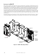
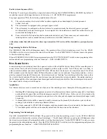
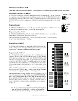
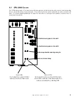
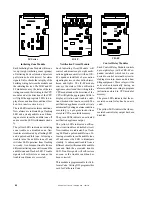
The Security Switch can
be found in one of two
locations on the CPU.
Write Inhibit
position
Write Enable
position
7.1
G
ENERAL
The control panel is programmed entirely by using the four switches on the CPU. The eight LEDs are used to show the
programmer the status of programming. Each of these LEDs has two states - flashing and steady. On the programming label,
two functions are associated with each LED. The function marked with an "F" is indicated by a flashing LED. The function
marked with a "S" is indicated by steady LED illumination.
7.2
P
REPARING
FOR
P
ROGRAMMING
Slide programming label into the Dress Panel. Insert the Programming Key through the dress panel into Plug J11 on the
CPU. Wait until ENTER PASSWORD LED and PRESS ENTER LED flash, then enter password.
7.3
E
NTERING
P
ASSWORDS
There are four different programming modes, each with its own password. They are as follows:
Reconfigure: 123-1231, System Programming: 123-1232, Extended Features: 123-3211, Clear Program 312-1233
After entering the appropriate password digits, press the ENTER switch.
7.4
C
LEAR
P
ROGRAM
(P
ASSWORD
312-1233)
Before reconfiguring the system, we recommend clearing the CPU's memory. To do this use the PROGRAM CLEAR
function. After PREPARING FOR PROGRAMMING enter the password 312-1233 then press and hold the ENTER key.
The LEDs on the modules will go through a scrolling sequence until finally only the ENTER PASSWORD and PRESS
ENTER LEDs are lit (approx. 10 sec.). PROGRAM CLEAR is now complete and the system is ready for reconfiguration.
NOTE: Program clear should only be executed on new systems or ones that have been significantly changed because all
previous programming will be removed!
7.5
R
ECONFIGURE
M
ODE
(P
ASSWORD
123-1231)
Upon entering the
Reconfigure Mode
, the CPU identifies what modules are in the system. The system must be reconfigured
the first time it is programmed and any time a module is removed or added. The
Reconfigure Mode
sets new modules to the
default conditions listed below (the program for modules that have been previously reconfigured remains unchanged)
No circuits are selected for waterflow, supervisory, or circuit verification.
No circuits are selected for coded output.
All notification appliance circuits are silenceable.
Control relays are non-silenceable.
All circuits are mapped for general alarm.
After entering the Reconfigure password and pressing CHANGE STATE key, the PASSWORD ACCEPTED LED and the
RECONFIGURE LED will illuminate. All correctly-installed modules will light their LEDs as follows:
IZ-8F:
All red and yellow LEDs
IZ-4F:
All red and yellow LEDs
IC-4F, ICE-4F:
Four green LEDs on left. All eight will light if an expander has been installed.
CR-4F, CRE-4F:
Four yellow LEDs on left. All eight will light if an expander has been installed
TC-2F, TC-4F:
All eight green LEDs will light.
Press the ESCAPE switch to store the system configuration. Programming will advance to programming of the system.


