background image

 15465 Rev F   5/2/97  P/N 15465:F

43

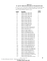
If "A or C" are entered for address 42, the following is automatically
programmed for the Secondary phone number event codes.  Enter '00'
for the Setting to disable the report.

Factory

Address      Description

Setting

156-157

Secondary # Zone 1 Alarm Code

1 1

158-159

Secondary # Zone 2 Alarm Code

1 2

160-161

Secondary # Zone 3 Alarm Code

1 3

162-163

Secondary # Zone 4 Alarm Code

8 4

164-165

Secondary # Zone 5 Alarm Code

1 5

166-167

Secondary # AC Fault Code

F 6

168-169

Secondary # Zone 1 Fault Code

F 1

170-171

Secondary # Zone 2 Fault Code

F 2

172-173

Secondary # Zone 3 Fault Code

F 3

174-175

Secondary # Zone 4 Fault Code

F 4

176-177

Secondary # Zone 5 Fault Code

F 5

178-179

Secondary # Earth Ground Code

F 7

180-181

Secondary # Low Battery Code

F 8

182-183

Secondary # No Battery Code

F 9

184-185

Secondary # Telco Prim. Line Fault Code

F A

186-187

Secondary # Telco Sec. Line Fault Code

F B

188-189

Secondary # Bell Fault Code

F C

190-191

Secondary # Comm Trouble Pri. #

F D

192-193

Secondary # Comm Trouble Sec. #

F E

194-195

Secondary # Annunciator Fault Code

F C

196-197

Secondary # System Off Normal Code

F F

198-199

Secondary # Zone 1 Alarm Restoral Code

E 1

200-201

Secondary # Zone 2 Alarm Restoral Code

E 2

202-203

Secondary # Zone 3 Alarm Restoral Code

E 3

204-205

Secondary # Zone 4 Alarm Restoral Code

E 4

206-207

Secondary # Zone 5 Alarm Restoral Code

E 5

208-209

Secondary # AC Fault Restoral Code

E 6

210-211

Secondary # Zone 1 Fault Restoral Code

E 1

212-213

Secondary # Zone 2 Fault Restoral Code

E 2

214-215

Secondary # Zone 3 Fault Restoral Code

E 3

216-217

Secondary # Zone 4 Fault Restoral Code

E 4

218-219

Secondary # Zone 5 Fault Restoral Code

E 5

220-221

Secondary # Earth Ground Restoral Code

E 7

222-223

Secondary # Low Battery Restoral Code

E 8

224-225

Secondary # No Battery Restoral Code

E 9

226-227

Secondary # Telco Prim.Line Fault Restoral

E A

228-229

Secondary # Telco Sec. Line Fault Restoral

E B

230-231

Secondary # Bell Fault Restoral Code

E C

232-233

Secondary # Comm Trouble Rest. Pri. #

E D

234-235

Secondary # Comm Trouble Rest. Sec. #

E E

236-237

Secondary # Annunciator Fault Restoral

E C

238-239

Secondary # System Return to Normal Mode

E F

240-241

Secondary # 24 Hour Test Code

9 9

242-243

Secondary # System Abnormal Test Report

9 1

Table 4.3-4:

4+2 Standard Format

Technical Manuals Online! - http://www.tech-man.com

firealarmresources.com

Summary of Contents for MS-5012

Page 1: ... CT 06472 Document 15465 Document 15465 Document 15465 Document 15465 Document 15465 5 2 97 Rev 5 2 97 Rev 5 2 97 Rev 5 2 97 Rev 5 2 97 Rev MS 5012 Control Communicator Installation Operation and Programming Manual Technical Manuals Online http www tech man com firealarmresources com ...

Page 2: ...p before handling any circuits so that static charges are removed from the body Use static suppressive packaging to protect electronic assemblies removed from the unit Follow the instructions in the installation operating and programming manuals These instructions must be followed to avoid damage to the control panel and associated equipment FACP operation and reliability depend upon proper instal...

Page 3: ... 28 Figure 3 3 2 Relays 29 3 4 UL Power limited Wiring Requirements 30 Figure 3 4 1 Typical Wiring for UL Power limiting 30 3 5 DigitalCommunicator 31 Figure 3 5 1 Wiring RJ31X 31 3 6 Operating Power 32 Figure 3 6 1 Power Connections 32 Figure 3 6 2 Optional AC Terminal Block Installation 33 3 7 OptionalModules 34 Figure 3 7 1 Installing the Annunciator 35 Figure 3 7 2 Wiring the RZA 5F ADM 12 35 ...

Page 4: ...ctuated Signaling Boxes UL 217 Smoke Detectors Single and Multiple Station UL 228 Door Closers Holders for Fire Protective Signaling Systems UL 268 Smoke Detectors for Fire Protective Signaling Systems UL 268A Smoke Detectors for Duct Applications UL 346 Waterflow Indicators for Fire Protective Signaling Systems UL 464 Audible Signaling Appliances UL 521 Heat Detectors for Fire Protective Signalin...

Page 5: ...15465 Rev F 5 2 97 P N 15465 F 5 Technical Manuals Online http www tech man com firealarmresources com ...

Page 6: ...en Collector Outputs 5 Input Zones Piezo 85dB Keypad 4 Digit LED Display Primary Secondary Phone Lines Slot for Annunciator Driver Module Holds up to 7AH Batteries Up to 60 Hrs of Standby Technical Manuals Online http www tech man com firealarmresources com ...

Page 7: ...Disable report by event Low AC Voltage Sense Walk Test Built in Voltmeter Built inProgrammer One NFPA Style Y Notification Appliance bell Circuit Optional Dead Front cover available The MS 5012 is a combination control panel and digital communicator all on one circuit board It is a five zone panel which uses conventional input devices The panel accepts waterflow devices two wire smoke detectors fo...

Page 8: ...ppliance Circuit Resettable Power Circuit Non Resettable Power Circuit Relay Driver Output Alarm Relay Driver Output Trouble Relay Driver Output Supervisory Relay Driver Output Communicator Failure Primary Telephone Line Secondary Telephone Line 12 Volt Battery Charger Reset Digits 0 9 Silence A Mode B Up Arrow C Down Arrow D 1st Event E Enter Store F Alarm red LED Trouble yellow LED Supervisory y...

Page 9: ... lines Listen for dial tone 440 hertz tone typical in most networks Dialing the Central Station s number default is Touch Tone programmable to rotary Discern proper Ack and Kiss off tone s The frequency and time duration of the tone s varies with the transmission format The control panel will adjust accordingly Communicate in the following formats 12 Tone Burst Types 20 pps 3 1 4 1 4 2 3 1 Exp 4 1...

Page 10: ...Remote Annunciator requires the use of the ADM 12 Annunciator Driver Module 1 7 Remote Annunciator ADM 12 Annunciator Driver Module The ADM 12 Annunciator Driver Module supports the RZA 5F Remote Annunciator module Annunciator wiring is supervised for open conditions by this module The Annunciator Driver Module mounts to the main board occupying one of the two option connectors RESET SILENCE MODE ...

Page 11: ...rm Current 12 mA Short Circuit Current 24 mA maximum Maximum Detector Current in Standby 2 mA Maximum Loop Resistance 30 ohms End of Line Resistor 2 2K 1 2 Watt part 27070 UL listed Detector Loop Current is sufficient to ensure operation of one alarmed detector per zone Standby Current 5 17 mA including ELR Notification Appliance Circuit TB3 Terminals 1 2 Power Limited Circuitry Operating Voltage ...

Page 12: ...ve 5 0 To be certain of the number of devices that may be connected to the line as determined by the total REN s contact the telephone company to determine the maximum REN for the calling area Digital Communicator Before connecting the control panel to the public switched telephone network the installation of two RJ31X jacks is necessary The following information is provided if required by the loc...

Page 13: ... notification will be provided as soon as possible The opportunity will be given to correct any problems and to file a complaint DO NOT CONNECT THIS PRODUCT TO COIN TELEPHONE GROUND START OR PARTY LINE SERVICES When the control panel activates premise phones will be disconnected Two separate phone lines are required Do not connect both telephone interfaces to the same telephone line The control pa...

Page 14: ...system and any smoke detectors If the Reset Switch is pressed the control panel will Clear the display and status LEDs Turn off the Notification Appliance Circuit Reset all zones by temporarily removing power Silence the on board piezo sounder Store reset message in the History file see Section 5 2 Clear all relay driver outputs Temporarily remove power from the resettable power output TB1 termina...

Page 15: ...he 1st event alarm and or trouble that occurred r r r r r Down arrow Use the down arrow switch to view other events older that have occurred and are active not cleared yet q q q q q Up arrow Use the up arrow switch to view other events newer that have occurred and are active not cleared yet Enter Store Not used in Normal Mode Four 7 segment red LED characters provide visual annunciation of status ...

Page 16: ...low LED that indicates need for action in connection with the supervision or maintenance of sprinklers extinguishing systems or other protective systems System Silence A yellow LED that indicates an Alarm or Trouble is being silenced Primary Line Active A red LED that indicates the primary phone line is active Secondary Line Active A red LED that indicates the secondary phone line is active Kiss O...

Page 17: ... at any time See History Mode Section 5 2 Higher priority events take precedence over lower priority events Display of System Activity is done on a priority basis Priorities are from highest to lowest 1 Alarms 2 Supervisory alarms 3 Faults troubles The highest priority event will be communicated to the central station first It also is displayed overriding any other displayed event only one is disp...

Page 18: ...eactivate the alarm relay driver TB3 4 Clear the 4 character display Send all Zone Restoral messages to the central station Turn off the Notification Appliance Circuit Turn off the Piezo Sounder System Supervisory Condition Zone 4 is factory programmed as a supervisory zone This zone is primarily used in applications where a waterflow sensing device has been employed and the wiring to the waterflo...

Page 19: ...l message to the central station Shut off the piezo sounder Trouble Conditions The control panel will perform the following upon detection of a trouble condition Turn on the trouble LED Activate the trouble relay driver TB3 5 The appropriate trouble message will be displayed Below are the trouble messages shown in priority fashion from the highest priority to the lowest AC F 1 F 3 F 2 F 5 F 4 F E ...

Page 20: ...tched telephone network Two supervised telephone line connections are made to interface the control panel to the telephone lines Two optional 7 foot telephone cords are available for this purpose See Figure 3 5 1 for proper wiring diagram The control panel supervises both telephone lines for proper voltage A delay of two minutes will occur before a fault in either phone line connection is reported...

Page 21: ...the format in use Tables 4 3 1 through 4 3 4 list these messages The table below shows the reporting structure for all of the tone burst type formats Table 2 4 1 Format Selection Addresses 16 42 Format 2 4 6 8 Format 3 5 7 9 Format A C Format B D Report 3 1 4 1 Standard 3 1 4 1 Expanded 4 2 Standard 4 2 Expanded Alarm SSS S A SSS S A AAA A Z SSSS AA2 SSSS AZ Alarm Restore SSS S RA SSS S RA RARARA ...

Page 22: ...RP2 AC Loss Restore 2nd digit V Supervisory Condition 1st digit V2 Supervisory Condition 2nd digit RV Supervisory Condition Restore 1st digit RV2 Supervisory Condition Restore 2nd digit X Test Report 1st digit X2 Test Report 2nd digit Y 6 AC Loss 7 Ground Fault 8 Low Battery 9 No Battery A Telco Primary Line Fault B Telco Secondary Line Fault C Main Bell Fault Annunciator Fault D Communication Fau...

Page 23: ...evel Pull Stations Waterflow Smoke Detector Other Alarm Types 2 Supervisory Zone 3 Faults AC Fail Zonal faults Earth fault Low battery No battery Telephone line fault Bell circuit fault Communication Trouble Annunciator Trouble 4 Restoral AC Zones Earth Battery Telephone Line Bell Communication Annunciator Trouble 5 24 Hour Test Lowest Priority Technical Manuals Online http www tech man com fireal...

Page 24: ...ftware and a memory card with Rev 3 8 software 5 Model 6500 with Rev 600 software 6 Model 6000 with Rev 204 software 7 With Rev B control card at rev 1 4 software and Rev C line card at rev 1 5 software 8 Version 1 62 software Ademco 685 1 Silent Knight 9000 ITI CS 4000 3 FBI CP220FB Osborne Hoffman Models 1 2 Table 2 4 2 Compatible UL Listed Receivers Radionics 6000 6500 5 Sescoa 3000R 7 Red LEDs...

Page 25: ...minals 1 2 It is power limited to 2 66 mA standby and 4 46 mA in alarm Factory Default is Pull Station Refer to Section 4 0 Programming Zone 2 is a Style B Initiating Device Circuit designed to accept any N O contact device and conventional 2 wire 12 volt smoke detectors on TB2 terminals 3 4 It s power limited to 7 17 mA in standby and 24 mA in alarm For a list of compatible 2 wire detectors refer...

Page 26: ...x 2 875 deep Metal gauge is 18 The metal finish is Fire Lite standard red Knock outs are provided on the top and sides to provide ease of wire entry Draw wires through the respective knockout locations Figure 3 2 1 Cabinet Dimensions Knockout Locations Technical Manuals Online http www tech man com firealarmresources com ...

Page 27: ...2 It s power limited to 2 66 mA in Standby and 4 46 mA in alarm Factory Default is 4 wire Smoke Detector Refer to Section 4 0 Programming Four wire smoke detectors may be connected to any zone Resettable power is provided via terminals TB2 13 and 14 See Figure 3 2 1 for proper connection of 4 wire detectors It is allowable to mix an assortment of device types on any zone however it is not recommen...

Page 28: ...ee Figure 3 3 1 For a list of compatible devices refer to the Fire Lite Compatibility Document A minimum 300mA load is required Provision is available to interconnect to two independent telephone lines Telephone line control command is possible via double line seizure as well as usage of an RJ31X style interconnection See Figure 3 5 1 Relay driver outputs are available for Alarm Trouble Supervisor...

Page 29: ...pervisory Off de energized TB3 7 Communications Failure Off de energized UL Recognized Enclosure Note Wiring from TB3 to Relays is power limited but not supervised Figure 3 3 2 Driving Relays from Open Collector Outputs Relays must be placed in a UL 864 recognized enclosure Wiring from the control panel s terminals on TB3 to the relays must be less than 3 feet in length enclosed in conduit Wiring ...

Page 30: ...ted circuit wiring Furthermore all power limited circuit wiring and nonpower limited circuit wiring must enter and exit the cabinet through different knockouts and or conduits A typical wiring diagram for the MS 5012 is shown below Power limited Circuits Power limited Circuits Power limited Circuits AC Power Figure 3 4 1 Typical Wiring Diagram for UL Power limited Requirements Technical Manuals On...

Page 31: ...properly function The control panel s digital communicator is built right into the main board All that is required to install the system is the connection and wiring of two phone lines as shown below Figure 3 5 1 Wiring Jacks 1 2 3 4 5 6 7 8 1 2 3 4 5 6 7 8 Tip Tip Ring Ring Green Wire Green Wire To premise phones To premise phones Red Wire Red Wire Ring Ring Primary Lines Incoming Telco Phone Lin...

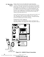
Page 32: ...cted to this circuit In addition this circuit must be provided with overcurrent protection and may not contain any power disconnect devices Connect the backbox ground stud to a solid earth ground a metallic cold water pipe may be suitable in some installations This connection is vital to maintaining the control panel s immunity to unwanted transients generated by lightning and electrostatic discha...

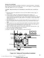
Page 33: ...k AC wire Hot is connected opposite the black transformer wire and the white AC wire Neutral is connected opposite the white transformer wire 4 Make certain that the yellow wires secondary from the MS 5012 system transformer are con nected to Terminal Block TB1 located in the lower left corner of the MS 5012 main circuit board 5 Install a jumper between the terminal block and the backbox ground st...

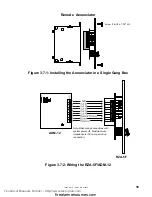
Page 34: ...rovides LED indication of the following Alarm Zone 1 red Alarm Zone 2 red Alarm Zone 3 red Alarm Zone 4 red Alarm Zone 5 red System Trouble yellow The remote annunciator provides individual zone alarm LEDs a system trouble LED a piezo sounder and a remote sounder shut off switch A Local Trouble Sounder and Silence Switch are also provided All LED wiring is supervised for open conditions Any open c...

Page 35: ...Annunciator in a Single Gang Box Note Make wiring connections with system power off Maximum wire impedance is 100 ohm per wiring connection ADM 12 RZA 5F Figure 3 7 2 Wiring the RZA 5F ADM 12 Remote Annunciator 12V Technical Manuals Online http www tech man com firealarmresources com ...

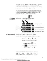
Page 36: ...umbers and 24 hour test report times for each Central Station account and the current time The control panel comes with factory chosen options features already programmed Other options features may be programmed if desired If all factory default settings are acceptable programming is complete To enter the Program Mode press the w key once the display will go blank you then have ten seconds to star...

Page 37: ...89d s a0bc t No function in this mode Increment memory address Decrement memory address Select operating mode Once First memory address Twice type any address Save data go to next address When in Programming Mode the trouble light will be on the trouble relay driver will be activated but the communicator will not be activated to report this trouble Transmissions started before entering program mod...

Page 38: ...z Carrier 2300 Hz ACK Table 4 3 1 8 4 1 Standard 1900 Hz Carrier 1400 Hz ACK Table 4 3 1 9 4 1 Expanded 1900 Hz Carrier 1400 Hz ACK Table 4 3 1 A 4 2 Standard 1800 Hz Carrier 2300 Hz ACK Table 4 3 2 B 4 2 Expanded 1800 Hz Carrier 2300 Hz ACK Table 4 3 1 C 4 2 Standard 1900 Hz Carrier 1400 Hz ACK Table 4 3 2 D 4 2 Expanded 1900 Hz Carrier 1400 Hz ACK Table 4 3 1 E Not Used F Not Used Note Consult y...

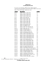
Page 39: ... F 86 Primary Comm Trouble Sec F 87 Primary Annunciator Fault Code F 88 Primary System Off Normal Code F 89 Primary Zone 1 Alarm Restoral Code E 90 Primary Zone 2 Alarm Restoral Code E 91 Primary Zone 3 Alarm Restoral Code E 92 Primary Zone 4 Alarm Restoral Code E 93 Primary Zone 5 Alarm Restoral Code E 94 Primary AC Fault Restoral Code E 95 Primary Zone 1 Fault Restoral Code E 96 Primary Zone 2 F...

Page 40: ...t Code F C 108 109 Primary System Off Normal Code F F 110 111 Primary Zone 1 Alarm Restoral Code E 1 112 113 Primary Zone 2 Alarm Restoral Code E 2 114 115 Primary Zone 3 Alarm Restoral Code E 3 116 117 Primary Zone 4 Alarm Restoral Code E 4 118 119 Primary Zone 5 Alarm Restoral Code E 5 120 121 Primary AC Fault Restoral Code E 6 122 123 Primary Zone 1 Fault Restoral Code E 1 124 125 Primary Zone ...

Page 41: ...enter a 1 into this address Programming the Secondary Phone Number 26 41 is similar to the primary phone number located in addresses 00 15 The defaults are also all F s 4 8 4 7 1 6 1 F F F F F F F F F 26 27 28 29 30 31 32 33 34 35 36 37 38 39 40 41 Programming Secondary Number Communication Format 42 is programmed the same way as the primary number s Comm Format in address 16 Default entry is A 4 ...

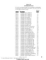
Page 42: ...condary Comm Trouble Sec F 175 Secondary Annunciator Fault Code F 176 Secondary System Off Normal Code F 177 Secondary Zone 1 Alarm Restoral Code E 178 Secondary Zone 2 Alarm Restoral Code E 179 Secondary Zone 3 Alarm Restoral Code E 180 Secondary Zone 4 Alarm Restoral Code E 181 Secondary Zone 5 Alarm Restoral Code E 182 Secondary AC Fault Restoral Code E 183 Secondary Zone 1 Fault Restoral Code ...

Page 43: ...6 197 Secondary System Off Normal Code F F 198 199 Secondary Zone 1 Alarm Restoral Code E 1 200 201 Secondary Zone 2 Alarm Restoral Code E 2 202 203 Secondary Zone 3 Alarm Restoral Code E 3 204 205 Secondary Zone 4 Alarm Restoral Code E 4 206 207 Secondary Zone 5 Alarm Restoral Code E 5 208 209 Secondary AC Fault Restoral Code E 6 210 211 Secondary Zone 1 Fault Restoral Code E 1 212 213 Secondary ...

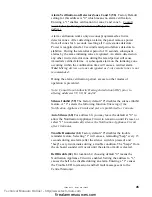
Page 44: ...tard Timer 53 54 This field allows you to select a delay of up to 89 seconds for declaring a Waterflow Alarm Factory default is one second The default for addresses 53 and 54 are 00 no additional delay Valid keys for 53 are 0 8 and 0 9 for 54 Program an entry into this address only if selecting a 0 in address 52 above Be careful to include any built in delays of the waterflow device Programming AC...

Page 45: ...her modes of operation is prevented Note Consult local Authority Having Jurisdiction AHJ prior to altering addresses 59 60 61 and 62 Silence Inhibit 59 The factory default 0 disables the silence inhibit feature A 1 selects the following function Silencing of the Notification Appliance Circuit and piezo is prohibited for 1 minute Auto Silence 60 For address 60 you may leave the default at 0 to allo...

Page 46: ...reak ratio is factory set to 0 which is 67 33 but may be changed to 1 which is a 62 38 ratio Programming Event Codes 68 243 Tables 4 3 1 to 4 3 4 list messages or event codes that are sent to the Central Station The selections made for the Primary Number Communication Format address 16 and the Secondary Number Communication Format address 42 automatically program addresses 68 243 with factory defa...

Page 47: ... to normal mode Programming the Real Time Clock Entering an address greater than 243 will cause a display of the current time On initial power up the clock will start running from the factory setting of 00 00 military time The far left digit will be flashing indicating that this will be the first digit to be programmed Simply enter the correct digits of the current time followed by enter store Tec...

Page 48: ...WALK on a Touch Tone phone Once in Walk Test Mode the MS 5012 will immediately Turn on the trouble LED Activate energize the trouble relay driver Turn on the Notification Appliance Circuit output for four seconds for the first alarm event on a zone Subsequent alarms will sound for one second Troubles cause the IAC to remain on Disable the alarm relay Display all alarm conditions as they occur Disp...

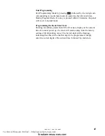
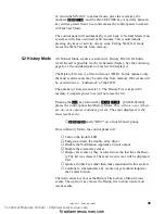
Page 49: ...mber of stored events is 16 The History File is kept in E2 memory Complete power loss will not erase the list Pressing the w key followed by 4478 ENTER STORE places the control panel into History Mode This will not occur if there are any active alarm conditions present The event displayed is the most recent event 4478 spells HIST on a Touch Tone phone Once in History Mode the control panel will Tu...

Page 50: ... open or short F E Earth Fault F A Annunciator Fault no 1 Primary Phone Line Fault no 2 Secondary Phone Line Fault rES Reset Switch pressed PH 1 Primary Number Communication Fault PH 2 Secondary Number Communication Fault no b No Battery Lo b Low Battery 51LE Silence Switch pressed To erase the list press the Silence key twice before exiting the History Mode A lack of keyboard activity for a perio...

Page 51: ... ENTER STORE will display the Battery Voltage Pressing 1 through 5 followed by ENTER STORE displays the zone voltage of the selected zone The q r and s keys do not function in this mode 5 3 Troubleshoot Mode Below is listed the nominal threshold voltages for each zone Zone Normal w E O L Shorted Open CKT 1 5 15V 0 15V 12 9V 2 11 75V 8 7V 12 9V 3 11 75V 8 7V 12 9V 4 5 15V 15V 12 9V 5 5 15V 15V 12 9...

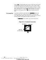
Page 52: ...ing c ENTER STORE a second time hangs up the call Repeated entries of c places the phone on and off hook To perform a Lamp Test press Mode then 5267 followed by ENTER STORE This will test all system LEDs except the Primary Active LED and Secondary Active LED The LEDs will stay on for five seconds then the control panel will return to normal mode 5267 spells LAMP on a Touch Tone phone 5 4 Lamp Test...

Page 53: ...3 54 Waterflow Reporting Delays Valid keys for field 53 are 0 8 and 0 9 for field 54 55 AC Loss Enter number of hours to delay reporting of AC loss 0 6 hours 1 7 hours 6 12 hours 56 Slave Comm Selection 0 for panel only set to 1 for slave operation 2 for fire control comm opera tion 57 Secondary Phone Number Enter 0 for secondary as a backup 1 to transmit always 58 Alarm Verify Enter 0 for no veri...

Page 54: ... 143 144 145 146 147 148 149 150 151 152 153 154 155 156 157 158 159 160 161 162 163 164 165 166 167 168 169 170 171 172 173 174 175 176 177 178 179 180 181 182 183 184 185 186 187 188 189 190 191 192 193 194 195 196 197 198 199 200 201 202 203 204 205 206 207 208 209 210 211 212 213 214 215 216 217 218 219 220 221 222 223 224 225 226 227 228 229 230 231 232 233 234 235 236 237 238 239 240 241 242...

Page 55: ...s 52 Zone 3 Function Select 0 Waterflow 53 54 Waterflow Reporting Delays No delay 55 AC Loss 6 hours 56 Slave Comm Selection 0 for panel only operation 57 Secondary Phone Number 0 secondary as a backup 58 Alarm Verify 0 no verification 59 Silence Inhibit 0 disable silence inhibit 60 Auto Silence 0 disable auto silence 61 Trouble Reminder 0 disable trouble reminder 62 Bell Disable 0 Bell enabled 63...

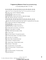
Page 56: ... 190 191 192 193 194 195 196 197 198 199 200 201 202 203 204 205 206 207 208 209 210 211 212 213 214 215 216 217 218 219 220 221 222 223 224 225 226 227 228 229 230 231 232 233 234 235 236 237 238 239 240 241 242 243 Programming Reference Sheet Factory Default Settings 1 1 1 2 1 3 8 4 1 5 F 6 F 1 F 2 F 3 F 4 F 5 F 7 F 8 F 9 F A F B F C F D F E F C F F E 1 E 2 E 3 E 4 E 5 E 6 E 1 E 2 E 3 E 4 E 5 E ...

Page 57: ... EF It is important to note that activation of Zone 2 in Slave Communicator Configuration will cause the yellow trouble LED to flash and the trouble sounder to pulse however the red alarm LED will not activate and the notification appliances will not sound Location 56 must be programmed to a 1 to enable the control panel as a slave communicator When programming the MS 5012 as a slave communicator ...

Page 58: ...he presence of the disconnect relay it is not possible to initially out of the box power up an MS 5012 from the battery AC power must first be applied for 6 seconds Once AC power is applied do not connect a low capacity battery less than 7 0 volts to the system When replacing a bad battery turn off AC power before connecting the new battery Relays in the Master FACP activate various input circuits...

Page 59: ...n Hours i e 5 min 0 084 hours ___________ Add Standby and Alarm Load for Required Ampere Hour Battery ___________ Multiply by the Derating Factor of 1 2 ___________ Total Ampere Hours AH Required ___________ Select a battery with a greater amp hour rating Notes NFPA 72 1993 Central Station Local and Proprietary Protected Premises systems require 24 hours of standby NFPA 72 1993 Auxiliary and Remot...

Page 60: ...Standby 12 VDC The MS 5012 provides regulated power for operating the fire alarm control panel operating external devices and operating the standby battery The power for operating external devices is limited Use Table A 1 standby or nonalarm and Table A 2 alarm to determine if external loading is within the capabilities of the power supply Note 1 CurrentdrawonlyifEnd of Linerelayisinstalledbetween...

Page 61: ... X 0 025 Auxiliary Outputs TB3 4 Alarm TB3 5 Trouble TB3 6 Supervisory TB3 7 Comm Fail 1 max 1 max 1 max 1 max X X X X 0 040 0 040 0 0 Notification Appliances X _____ Notification Appliances X _____ Additional Current Draw from TB 3 alarm current Sum Column for Alarm Load Amps Note 1 Current shown is with all LEDs illuminated 2 Use compatible listed power supervision relay only 1 1 2 Technical Man...

Page 62: ...off 24 L Lamp Test 51 M Messages 49 Mounting Options 25 O Optional Boards 10 P Power Calculations 58 Primary Phone number 36 Programming Mode 35 R Relays 29 Remote Annunciator 10 33 34 S Secondary Phone Number 40 43 Slave Communicator Configuration 56 Switches 8 14 36 1st Event 15 Enter Store 15 Mode Switch 15 Silence Switch 15 T Troubleshoot Mode 50 W Walk Test Mode 47 Wiring Jacks 31 Technical M...

Page 63: ...15465 Rev F 5 2 97 P N 15465 F 63 Technical Manuals Online http www tech man com firealarmresources com ...

Page 64: ...de by Fire Lite with respect to its products Fire Lite does not represent that its products will prevent any loss by fire or otherwise or that its products will in all cases provide the protection for which they are installed or intended Buyer acknowledges that Fire Lite is not an insurer and assumes no risk for loss or damages or the cost of any inconvenience transportation damage misuse abuse ac...

Reviews:

Related manuals for MS-5012