Fimco ATV-25-71 Owner'S Manual Download Page 5

Page 5 


Step 7 

Step 8 

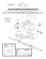
Assembly Procedure (ATV-25-71) 

*** The Sprayer should now be ready for use *** 

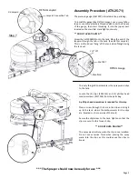
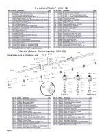
The pressure gauge (5167097) is located in the parts bag. 
 
To install the gauge (See DETAIL Gauge), wrap some Teflon 
tape or use some plumbers thread sealant over the threads 
of  the  gauge,  then  start  threading  it  into  the  (open)  port 
located on the manifold. Hand tighten securely. 
 

** DO NOT OVER-TIGHTEN ** 

 
Screw the lid (5058188) onto the tank. Place the end of the 
lanyard through the tab in the tank. (See DETAIL Lanyard). 
This is so the lid can ‘hang’ off the tank when filling/rinsing 
the tank out. 

Lid Lanyard 

Lanyard Connection Tab 

DETAIL Lanyard 

DETAIL Gauge 

1/4” FPT 

5167097 

Manifold 

The only thing left to assemble is the spray wand clips 
to the tank. 
 
Locate  the  (2)  clips  (5053112)  and  (2)  phillips  head 
machine screws (5117334) from the parts bag. 
 

A phillips head screwdriver is required for this step 
 

Place a screw through the hole in the clip and bring it 
up to the tank, where the embossments for the clips 
are  (located on the rear side of the tank) 
 
Secure the clip/screw to the tank. Tighten so that the 
clip is secure. Do this for each clip. 


** DO NOT OVER-TIGHTEN **


The spray wand will snap into the clips once installed. 
Do  not  use  excessive  force  when  placing  the  spray 
wand  into  the  clips,  as  this  could  cause  the  clips  to 
break. 

Summary of Contents for ATV-25-71

Page 1: ...ee Fax 800 494 0440 5004550 06 15 Model ATV 25 71 5301159 25 Gallon Deluxe Lawn Garden ATV Sprayer Caution Always check the vehicle load rating before using this sprayer The loaded weight of the sprayer and boom assembly is about 280 lbs when the tank is full Care must be taken not to tip the vehicle over back wards especially when starting or accelerating Technical Specifications 25 Gal Corrosion...

Page 2: ...of your sprayer s carton ATV 25 71 5301159 7 Nozzle Boom 5274770 7 Nozzle Harness 5277765 Contents of Parts Bag 5278307 Tank Lid Lanyard 5058188 Tank Plumbing Pre Assembly Owner s Manual Contents of Bracket Kit 5275935 ...

Page 3: ...ace with the whiz nuts 5006307 You can position them as needed within the slot on the tab Make sure the threads of the u bolts do not puncture the tank at any point Manually adjust the u bolts slightly if they get too close to the tank Do this prior to fully tightening the brackets to the rack Detail A shows the RH side bracket in the middle of the slot If you were to position this bracket at this...

Page 4: ...e harness can now be attached Attach the nozzle harness to the boom Each nozzle body has a brass nut which holds it to the steel boom Make sure these are tightened securely After your nozzle harness is attached to the boom locate the 48 hose 5020122 and the 2 hose clamps 5051144 from the parts bag Place the hose clamps over each end of the hose loosely Slip the ends of the hose over the hose barbs...

Page 5: ...ng rinsing the tank out Lid Lanyard Lanyard Connection Tab DETAIL Lanyard DETAIL Gauge 1 4 FPT 5167097 Manifold The only thing left to assemble is the spray wand clips to the tank Locate the 2 clips 5053112 and 2 phillips head machine screws 5117334 from the parts bag A phillips head screwdriver is required for this step Place a screw through the hole in the clip and bring it up to the tank where ...

Page 6: ...spraying Using the Boom Nozzles Four things must be considered before spraying with the boom How much chemical must be mixed in the tank Rate of spray gallons per acre to be sprayed What pressure p s i will be used Speed traveled mph while spraying Refer to the chemical label to determine your chemical mixture See the tip chart to determine the pressure to be used The chart will also show the spee...

Page 7: ... pumped through the plumbing system and out through the spray nozzles Refill the tank about half full with plain water and use FIMCO Tank Neutralizer and Cleaner and repeat cleaning instructions above Flush the entire sprayer with the neutralizing cleaning agent then flush out one more time with plain water Follow the chemical manufacturer s disposal instructions of all wash or rinsing water For t...

Page 8: ...eir terminals and touch the two ends together If your pump runs when you do this your pressure switch will need to be replaced Check the fuse Check for low voltage at the power supply Pump does not prime Check for air leaks in supply line Check for debris in the check valve assembly Check for defective check valve Check for clogged strainer filter Check for cracks in the pump housing Check for emp...

Page 9: ...Page 9 Intake Detail 5275877 Manifold Detail 5302349 Exploded View ATV 25 71 5301159 Typical Spray Pattern 7 Nozzle Boom ...

Page 10: ...Page 10 Parts List ATV 25 71 5301159 LH Elbow Tee RH Elbow 7 Nozzle Deluxe Boom Assembly 5301164 Opposite side has typical hardware setup ...

Reviews: