Page 15
NOTES:
This sprayer comes with an On/Off (shut-off) valve located
at the inlet location of the tank, towards the underside. You
must make sure the valve is in the “open” position before
using your sprayer.
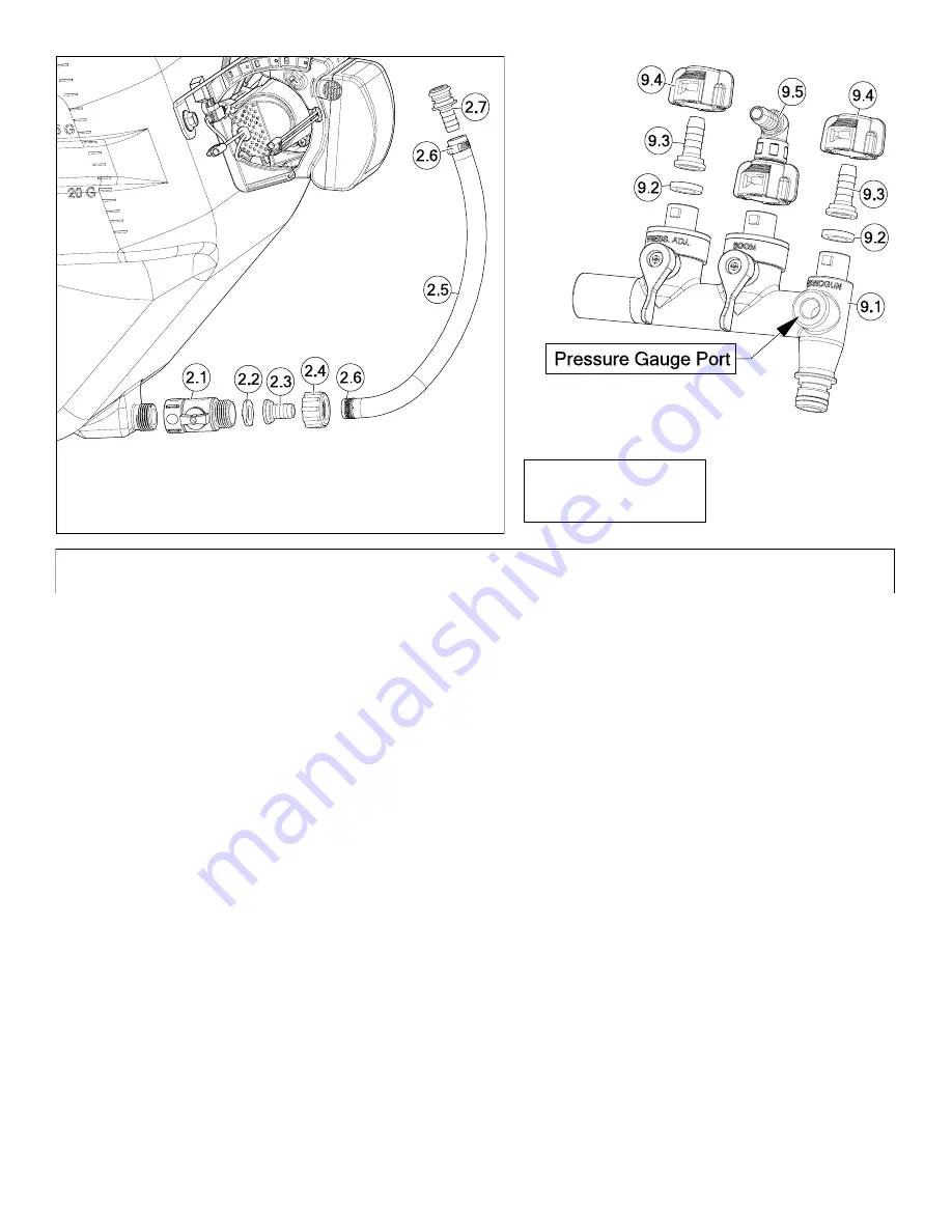
See Page 13
for Part Numbers
Manifold
Detail
Intake
Detail


