background image


Doc.


No.


06

916

 ●


Rev.


1


ISO


9001:2015


Certified


Page


1


of


7


Quick


Start


Guide


FIKE FLAME DETECTOR SETUP 


1.


General


The


purpose


of


this


guide


is


to


outline


how


to


perform


the


basic


setup


of


the


Fike


Flame


detectors


listed


below.


FIK

IR3


Flame


Detector


FIK

IR3

H2


Triple


IR


Hydrogen


Flame


Detector


FIK

IR3

H2

HD


Triple


IR


Hydrogen


Flame


Detector


FIK

IR3

HD


Triple


IR


Flame


Detector


FIK

UV

IR


Flame


Detector


FIK

UV

IR

HD


Flame


Detector


FIK

UV

IR

F


Flame


Detector


FIK

UV

IR

F

HD


Flame


Detector


Detector


setup


is


best


accomplished


before


the


installation


of


the


detector


using


the


methods


outlined


in


this


guide.


2.


Required


Hardware


and


Software


1.


Fike


flame


detector

1


2.


Computer


(desktop


or


laptop)

2,3


3.


Ethernet


switch

1,2


4.


24

volt


power


supply

2


5.


Ethernet


cable,


CAT5

2


6.


USB


to


RS

485


converter,


P/N


FIK

USB/RS485

1


7.


RS

485


cable

2


8.


24


VDC


power


supply


cable,


12

20AWG


(2.5

0.35mm

2

)

2


1

Available


for


purchase


from


Fike.


2

Supplied


by


others.


3

Can


use


Fike


NVR


or


Server.


Go


to


www.fg

detection.com/communicator


to


download


the


latest


version


of


the


Communicator


software.


Contact


Fike


at


1

800

979

3453


for


the


password.


3.


Detector


Connections


Connections


to


the


flame


detector


for


configuration


and


setup


will


vary


depending


upon


whether


the


detector


is


capable


of


providing


a


video


output.


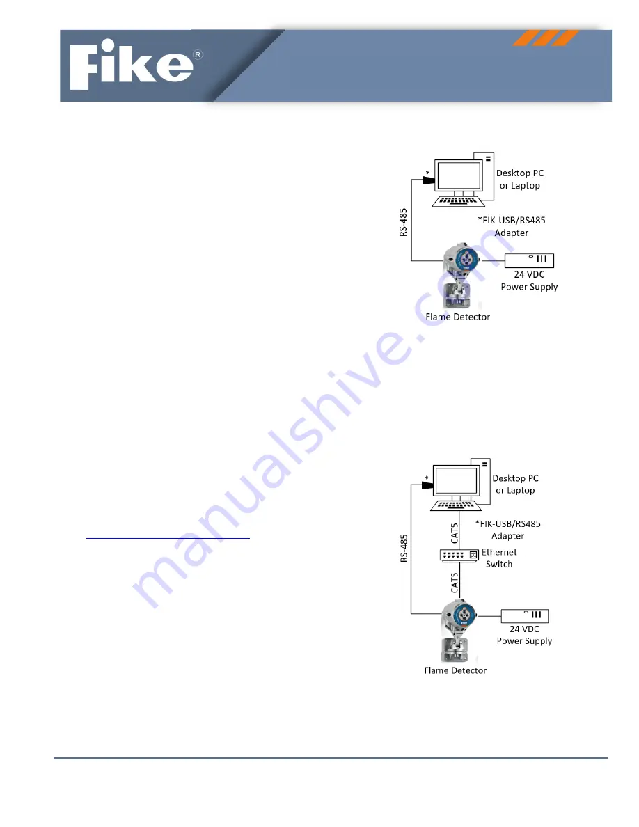
To


configure


a


detector


not


equipped


with


video


output


capabilities,


simply


connect


the


detector


to


the


host


PC


(desktop


or


laptop)


using


RS

485


cable


and


connect


a


24


VDC


power


source


to


the


detector


(Figure


1).


A


Fike


USB


to


RS

485


converter


(sold


separately)


must


be


used


to


allow


the


RS

485


cable


to


be


connected


to


the


host


PC’s


USB


port.


See


USB


to


RS

485


Converter


Wiring


for


details.


See


Table


1


for


detector


terminal


block


wiring


connections.


Applicable


to


FIK

IR3,


FIK

IR3

H2,


FIK

UV

IR


and


FIK

UV

IR

F


flame


detectors


Figure


1:


Connections


for


flame


detectors


without


video


output


To


configure


a


detector


equipped


with


video


output


capabilities,


the


detector


must


be


connected


to


the


host


PC


using


CAT5


cable


routed


through


an


Ethernet


switch


(Figure


2).


See


Table


2


for


detector


terminal


block


wiring


connections.


Applicable


to


FIK

IR3

H2

HD,


FIK

IR3

HD,


FIK

UV

IR

HD,


and


FIK

UV

IR

F

HD


flame


detectors


Figure


2:


Connections


for


flame


detectors


with


video


output


Summary of Contents for FIK-IR3

Page 1: ...test version of the Communicator software Contact Fike at 1 800 979 3453 for the password 3 Detector Connections Connections to the flame detector for configuration and setup will vary depending upon...

Page 2: ...tion Ground Ground earth Connected to a screw on the housing exterior 1 24 VDC Power supply 18 32 VDC 2 24 VDC Power supply return 0 VDC 3 0 20mA in 0 20 mA analog current ouput 4 0 20mA out 5 Fault R...

Page 3: ...et RX 19 Ethernet RX 20 Shield Permanent connection to detector housing internal ground Note Highlighted pins indicate required connections 6 Detector Configuration The RS 485 connection from the flam...

Page 4: ...User Manual for a detailed description of each configuration setting Figure 5 FGD Communicator detector configuration screen Table 3 Detector configuration options Function Options Default Setting Sen...

Page 5: ...address can even change while it is still connected 1 If a static IP address is required connected to the detector and open the Communicator software Locate the Ethernet IP address of the connected de...

Page 6: ...soft or hard reset is used it will default the camera settings to factory defaults Reboot simply restarts the camera Change the camera s time The time will be displayed on the camera s video feed Ass...

Page 7: ...d the 0 20mA signal will be sent If the lens is cleaned within 20 minutes the fault relay will open and the 0 20mA signal will return to normal The options in the Main and Secondary stream groups allo...

Reviews: