________________________________________________________________________________________________________________
12-20-2002
Figure Sheet 1-851-A
Page 5
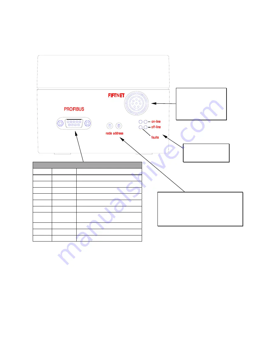
SBPC-21-PB External Connections/Switches/Indicators
SBPC-21-PB mounting considerations are simplified as all connections to the SBPC-21-PB are on the
same side of the box. The node address and rotary switches are accessible after removal of the plastic
hole plugs which should be reinstalled after configuration is completed.
Figure 1-3: SBPC-21-PB Side View
Profibus DP Baud Rate
The baud rate on a Profibus DP network is set during configuration of the master. Only one baud rate
is possible in a Profibus DP installation. The SBPC-21-PB uses auto baud rate detection so the user
does not have to configure the baud rate. Baud rates supported are:
•
9.6 kbit/s
•
187.5 kbit/s
•
3 Mbit/s
•
19.2 kbit/s
•
500 kbit/s
•
6 Mbit/s
•
93.75 kbit/s
•
1.5 Mbit/s
•
12 Mbit/s
Connection to FifeNet is
accomplished using the
standard FifeNet
connector. Configuration
is also downloaded using
this connection.
LED indicators provide
feedback for network
troubleshooting.
The Profibus Node address is set using these
rotary switches. This enables address settings
from 1-99 in decimal format. The left switch
sets the most significant digit and the right
switch sets the least significant digit. The node
address cannot be changed during operation.
D-SUB Connector
Pin Name
Signal
Housing
Shield
Connected to PE.
1
Not
connected
2
Not
connected
3 B-Line
Positive
RXD/TXD
4
RTS
Request to Send
1
5
GND BUS
Isolated GND from RS-485 side
1
.
6
+5V BUS
Is5VDC from RS-485
side3
1
.
7
Not
connected
8 A-Line
Positive
RXD/TXD
9
Not
connected
1
+5V Bus and GND Bus are used for bus termination. Some
devices, like optical transceivers (RS485 to fiber optics), might
require external power from these pins. RTS is used in some
equipment to determine the direction of transmission. In normal
applications only A-Line, B-Line, and Shield are used.


