18
CAS BACnet Setup
These are the instructions to set CAS Explorer up for the
first time on BACnet MS/ST and BACnet/IP.
CAS BACnet MS/TP Setup
1. Using the Serial or USB to RS-485 converter,
connect it to your PC and the 3 Pin BACnet MS/TP
connector on the ProtoNode RER.
2. In CAS Explorer, do the following:
a. Click on settings.
b. Check the BACnet MSTP box and uncheck the
BACnet IP and BACnet Ethernet boxes.
c. Set the BACnet MSTP MAC address to 0.
d. Set the BACnet MSTP Baud Rate to 38400.
e. Click OK.
f. On the bottom right-hand corner, make sure that
the BACnet MSTP box is green.
g. Click on discover.
h. Check all 4 boxes.
i. Click Send.
CAS BACnet BACnet/IP Setup
1. Set the IP address and subnet of the PC that will be
running the CAS Explorer.
2. Connect a straight through or cross Ethernet cable
from the PC to the ProtoNode.
3. In CAS Explorer, do the following:
a. Click on settings.
b. Check the BACnet IP box and uncheck the
BACnet MSTP and BACnet Ethernet boxes.
c. In the “Select a Network Device” box, select the
network card of the PC by clicking on it.
d. Click OK.
e. On the bottom right-hand corner, make sure that
the BACnet IP box is green.
f. Click on discover.
g. Check all 4 boxes.
h. Click Send.
7. APPENDIX A.
TROUBLESHOOTING
Check Wiring and Settings
1. No COMS on Modbus RTU side. If the Tx/Rx LEDs
are not flashing rapidly then there is a COM issue. To
fix this, check the following:
o Visual observations of LEDs on ProtoNode
(Section 8)
o Check baud rate, parity, data bits, stop bits.
o Check device address.
o Verify wiring.
o Verify the device was listed in the Web
Configurator (Section 6).
• Field COM problems:
o Visual observations of LEDs on the ProtoNode
o Verify IP Address setting
o Verify wiring
NOTE:
If the problem persists, a Diagnostic Capture
needs to be taken and sent to support. (Section A)
Take Diagnostic Capture With
the FieldServer Utilities
NOTE: When there is a problem on-site that cannot
easily be resolved, perform a Diagnostic Capture
before contacting support. Once the Diagnostic
Capture is complete, email it to technical support. The
Diagnostic Capture will accelerate diagnosis of the
problem. Once the Diagnostic Capture is complete,
email it to [email protected]. The Diagnostic
Capture will allow us to rapidly diagnose the problem
.
If the FieldServer bios is updated/released on November
2017 or later, then the Diagnostic Capture is performed via
the gateway’s on-board system.
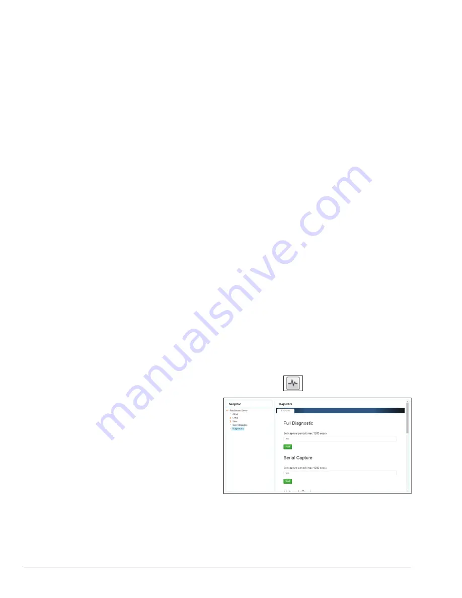
• Access the FieldServer Diagnostics page via one of
the following methods:
o Open the FieldServer FS-GUI page and click on
Diagnostics in the Navigation panel.
o Open the FieldServer Toolbox software and click the
diagnose icon
of the desired device.
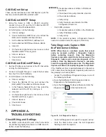
Figure 22. Full Diagnostics Screen
• Go to Full Diagnostic and select the capture period.
• Click the Start button under the Full Diagnostic
heading to start the capture.
APPROVED
UNCONTROLLED DOCUMENT IF PRINTED


