


2 - 15
Installation Procedures
Serial Port Connectors
COM1 (9-pin D-sub male connector with teal color) and COM2 (9-pin male
connector) allow you to connect with your devices that use serial ports, such
as a serial mouse or an external modem.
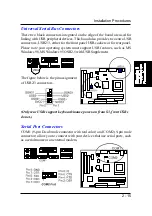
Universal Serial Bus Connectors
These two black connectors integrated on the edge of the board are used for
linking with USB peripheral devices. This board also provides two extra USB
connectors, USB2/3, either for the front panel USB sockets or for rear panel.
Please note your operating system must support USB features, such as MS
Windows 98, MS Windows 95 OSR2.5 with USB Supplement.
The figure below is the pin assignment
of USB2/3 connectors.
(Only rear USBs support keyboard/mouse power-on from S3, front USBs
do not.)
Summary of Contents for FR33E
Page 1: ...FR33E MAINBOARD MANUAL DOC No M01503 Rev A0 Date 9 2001 Part No 25 11620 00 ...
Page 7: ...1 3 Overview The FR33E Mainboard ...
Page 12: ...2 2 FR33E Mainboard Manual Mainboard Layout Quick Reference from Page 2 2 to 2 4 ...
Page 13: ...2 3 Installation Procedures 1 Clear CMOS Enable 2 Front Panel Block Cable Connection ...


