


Advanced FE/E1 Fiber Converters
13
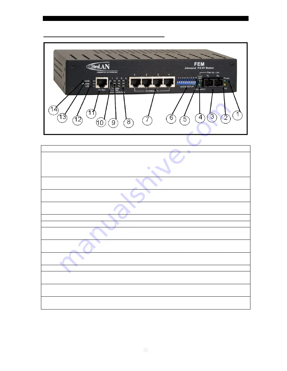
5 – Front Panel (Parts Identification)
1.Power ON LED:
(Power On/Off green LED indicator)
2.LAN LED
: lit (amber) implies (DIP Switch#10 UP):
LAN (switch) mode
of operation
of the TP ports. LED OFF (DIP Switch#10 Down):
Aggregator mode:
each Ethernet port forms a separate traffic path with the F/O port
Note: this LED is not present in the FEM4 models
3
.
Duplex SC fiber optic connector
: (left /Tx & right / Rx)
The port is configured by default to operate at 100Mb Full Duplex.
4
.
Link Partner LED:
(green)
lit implies that a link has been established with the
remote attached device
5
.
F/O Link/Activity LED
(green): constant lit: F/O Link present. Blinking implies
Activity (transmits or receives data).
6
.
Mode Setup
: Array of 10 DIP switches (see DIP switches setting – section 11)
7
.
RJ45 – Ethernet ports 1 to 4 connectors
8. Link
/
Activity
: LED (green, for each TP port) constant lit implies TP link present:
When blinking implies data activity (transmits or receives mode).
9
.
FDX LED
(green): Full Duplex indicator for ports 1-4: lit when FDX detected
10.100M LED
(amber): TP ports 100M: lit when 100Mbps detected or forced (TP port
1 via DIP switch S9)
11. E1 port: RJ-45, 120ohm, up to ~ 2Km
12. LED LOS (Loss of signal): lit red when a signal is not present at the local E1
port
13. LED REMOTE: lit green when a signal is present at the E1 port of the remote
FEM
attached device
(not present in FEM4 models)
14. LED LOCAL: lit green when a signal is present at the local E1 port
(not present in FEM4 models)
Each E1 port in FEM4 devices includes two LEDs:
LOS
(red) = Loss of signal
Signal
(green) = a signal is present at the local related E1 port


