L831-EA Module Hardware User Manual
Page 20 of 43
CONFIG_3
1
Figure4- 2 Pins Definition (Top View)
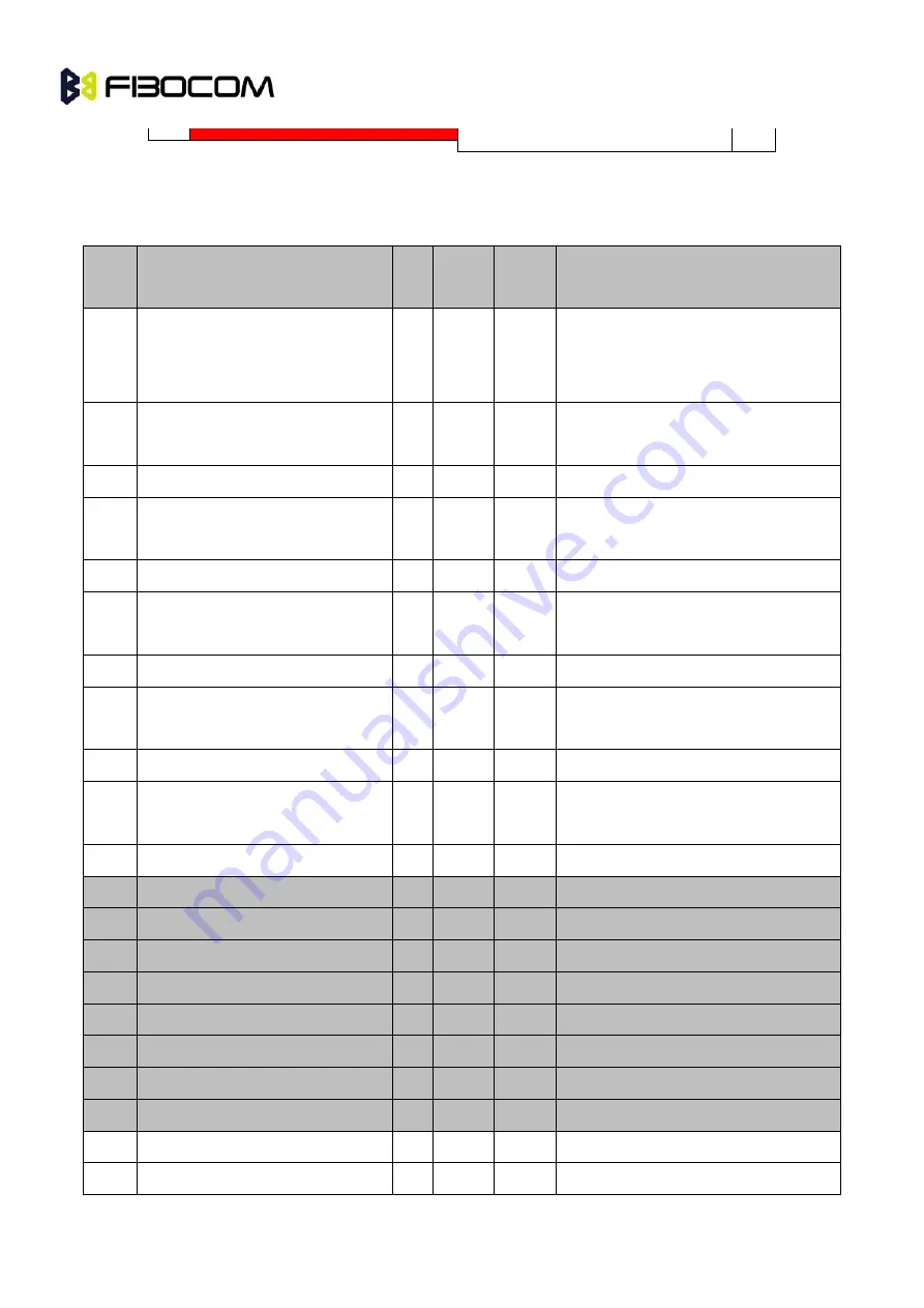
4.1.2 Pins Description
The description of L831-EA pins as listed below:
Pin#
Name
I/O
Reset
Value
Idle
Value
Description
1
CONFIG_3
O
L
L
The internal connects with GND, the
interface type of L831-EA module is
WWAN-SSIC0.
2
+3.3V
PI
The main power input, the voltage
range is: 3.135V ~ 4.4V
3
GND
GND
4
+3.3V
PI
The main power input, the voltage
range is: 3.135V ~ 4.4V
5
GND
GND
6
FUL_CARD_POWER_OFF#
I
PU
PU
Off control signal
,
the internal 200K
ohm will be pulled down, CMOS 1.8V
7
USB D+
I/O
USB 2.0
8
W_DISABLE1#
I
PU
PU
WWAN Disable, Low active, CMOS
3.3V
9
USB D-
I/O
USB 2.0 signal-
10
LED1#
O
OD
OD
System status LED
,
drain output, low
level is available, CMOS 3.3V
11
GND
GND
12
Notch
Notch
13
Notch
Notch
14
Notch
Notch
15
Notch
Notch
16
Notch
Notch
17
Notch
Notch
18
Notch
Notch
19
Notch
Notch
20
I2S_CLK
O
T
T
I2S serial clock
,
CMOS 1.8V
21
CONFIG_0
O
NC
NC
NC
,
the interface type of L831-EA


