LINOVISION IOT-CPE5G, Quick Start Manual
Introducing the LINOVISION IOT-CPE5G, a cutting-edge product in the world of IoT. Get started with ease using our comprehensive Quick Start Manual, available for free download on our website. Discover the power and functionality of our product today and obtain your manual from manualshive.com.
Share
Download


Reviews:
No comments
Related manuals for IOT-CPE5G
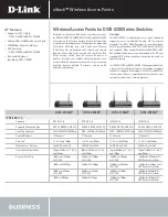
DWL-7130AP - xStack - Wireless Access Point
Brand: D-Link Pages: 4

6388
Brand: Paradyne Pages: 86

UDM-B
Brand: Ubiquiti Pages: 13

BreezeNET BU
Brand: Alvarion Pages: 9

UniFi AC Mesh
Brand: Ubiquiti Pages: 24

E220-900MM22S
Brand: Ebyte Pages: 14

E5783-330
Brand: Huawei Pages: 21

E5377
Brand: Huawei Pages: 7

E5573s-320
Brand: Huawei Pages: 28

E5786
Brand: Huawei Pages: 36

E6878-370
Brand: Huawei Pages: 22

E6878-870
Brand: Huawei Pages: 8

E5786s
Brand: Huawei Pages: 24

E5377
Brand: Huawei Pages: 34

E5785
Brand: Huawei Pages: 64

E5377Bs-508
Brand: Huawei Pages: 32

E5573Cs-322
Brand: Huawei Pages: 20

E5830s
Brand: Huawei Pages: 2


