http://www.fiberstars.com 79-15053-00 REV. C
Page 10 of 16
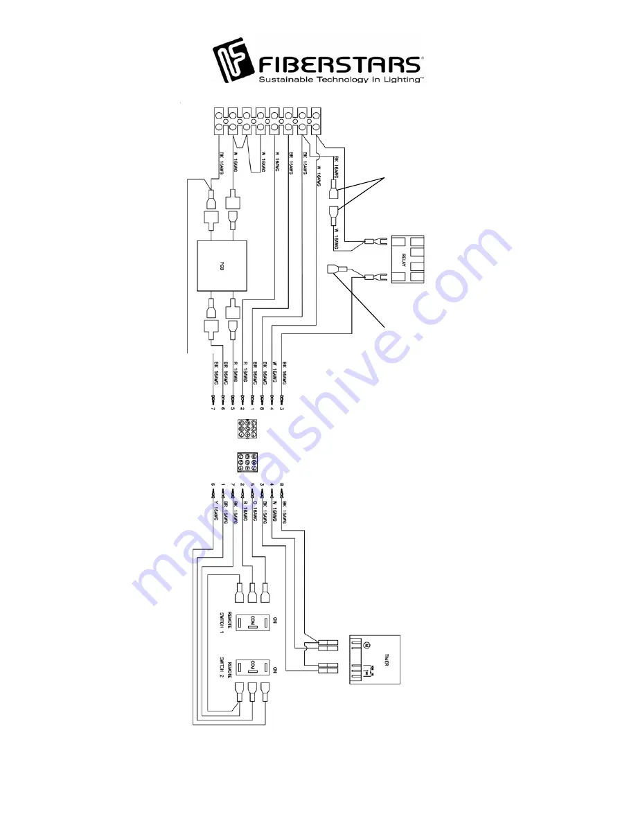
FOR TEMPERATURE FREEZE PROTECT SWITCH OPTION
FOR USE ON WPC-2 AUXILIARY RELAY KIT
Page 1: ...Instructions Read these instructions in their entirety before performing any installation work Rated for use on 110 120VAC 60Hz and 220 240VAC 60Hz applications WPC 1 ETL LISTED Conforms to UL STD 508...
Page 2: ...Door 3 1 37 15000 00 Relay 4 1 41 15004 08 8 Position Terminal Block 5 1 42 15032 00 Timer 6 1 02 15268 00 Face Plate 7 2 02 15274 00 WPC 1 Mounting Bracket 8 1 41 15003 00 Grounding Bar 9 1 94 15090...
Page 3: ...The Pump Relay is rated at a maximum of 3HP 240VAC Basic safety precautions should be observed when operating the WPC 1 product and other associated equipment 1 A qualified electrician must install th...
Page 4: ...nputs NEUTRAL terminal Connect another HOT wire to the Timeclocks T C POWER terminal Connect a house common to the Timeclocks T C NEUTRAL Install a 20 Amp circuit breaker in the main breaker panel and...
Page 5: ...HOT terminal on the POWER INPUT of the WPC 1 Connect the NEUTRAL from the LOAD side of the GFCI to the NEUTRAL terminal from the WPC 1 Connect the GROUND of the GFCI to the EQUIP GND bar Wire the HOT...
Page 6: ...rcuit 1 and Circuit 2 switch pull wires from the products to the WPC 1 through conduits connected to the bottom of the WPC 1 As illustrated connect lights that will be operated by the Circuit 1 Switch...
Page 7: ...nect the neutral to the NEUTRAL terminal in the WPC 1 and to the WHITE wire on the Fiberstars unit Connect the grounding cable to the EQUIP GND and on the other end to the GREEN cable Finally for sync...
Page 8: ...e 120V PRI INPUT terminal Directly connect the 120V Secondary from the Circuit Breaker to the 2 Speed Pump NOTE The Secondary 120V must be directly connected to the pump for 240V operation 240VAC Pump...
Page 9: ...he 24V TO VALVE terminal Connect the Close wire to the NC LOAD terminal and the Open wire to the NO LOAD terminal TO HEATER TO HEATER Heater Connection Optional Equipment To connect a heater run the p...
Page 10: ...http www fiberstars com 79 15053 00 REV C Page 10 of 16 FOR TEMPERATURE FREEZE PROTECT SWITCH OPTION FOR USE ON WPC 2 AUXILIARY RELAY KIT...
Page 11: ...to groove between the Dome and Base approximately where the locking dimples are located Pry the Dome out of on of the locking dimples Then carefully insert the small flathead screwdriver into the groo...
Page 12: ...enable the wireless remote operation flip the switch back to the REMOTE position NOTE If the units turn ON when the switch is returned to the REMOTE position simply use the wireless remote to turn OF...
Page 13: ...NOTE Each tab represents 15 minutes of operation and tabs set inwards towards the center is for OFF operations and ON when the tabs are set outwards as illustrated In the example below the Pump will b...
Page 14: ...a safe location where it will not be bent scratched or impact forces applied to the components or the face plate itself Unscrew the four 4 screws holding the receiver to the base of the WPC 1 control...
Page 15: ...F OFF Channel 4 ON ON OFF OFF Channel 5 OFF OFF ON OFF Channel 6 ON OFF ON OFF Channel 7 OFF ON ON OFF Channel 8 ON ON ON OFF Channel 9 OFF OFF OFF ON Channel 10 ON OFF OFF ON Channel 11 OFF ON OFF ON...
Page 16: ...T C Removed EXAMPLE WPC1 2X2X 1 is a 2 speed pump model with the Low Speed ON continuously until High Speed is actuated by the Time Clock Button 1 Circuit 1 is wired standard Button 2 Circuit 2 is wir...