4.3 p
osItIonIng
tHe
compressor
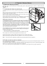
Once the position in which the compressor is to be installed has been identified ensure that the
compressor is set on a flat surface.
No special foundations or bases are required for the machine.
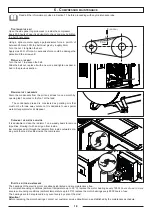
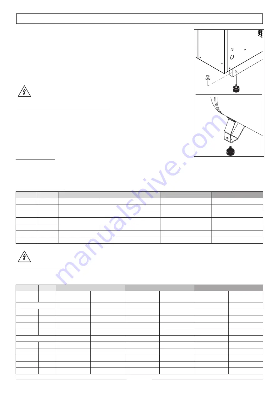
Lift the compressor using a forklift truck (forks at least 900 mm long) and fit the vibration-dam-
ping feet and block with the nuts under the four resting points where established.
Models on tank are supplied with rubber feet.
Do not secure the compressor rigidly to the floor.
4.4 c
onnectIng
tHe
compressor
and
relatIve
InspectIons
c
onnectIng
tHe
compressor
to
tHe
electrIcal
maIns
power
supply
The compressor is to be connected to the electrical mains by the customer, to his
exclusive liability, employing specialised personnel and in compliance with the Acci-
dent Prevention Norms EN 60204.
INSTRUCTIONS FOR CONNECTING TO EARTH
This compressor must be connected to earth while in use in order to safeguard the operator
against electrical shocks.
The electrical connection must be carried out by a skilled engineer. It is advisable never to di-
smantle the compressor or even to make any other connections.
All repairs must be carried out exclusively by authorised service centres or other qualified cen-
tres. The earth wire of the power supply cable of the compressor must be connected only and
exclusively to the PE pin of the terminal board of the actual compressor. Before replacing the
plug of the power supply cable ensure that the earth wire is connected.
EXTENSION CABLE
Use only extension cables with plug and earth connection. Never use damaged or squashed
extension cables. Ensure that the extension cable is in a good state of wear. When using an extension cable, ensure that the cross
section of the cable is sufficient to convey the current absorbed by the product to be connected.
If the extension cable is too thin there could be drops in voltage and therefore loss in power and overheating of the equipment.
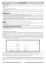
The extension cable of the three-phase compressors must have a cross section in proportion with its length: see table below:
Valid for max lenght 20 m
HP
kW
220-240V/50-60Hz
380-415 V/50-60Hz
460V/60Hz
3
2,2
2,5 mm²
-
1,5 mm²
-
4
3
4 mm²
-
2,5 mm²
-
5�5
4
4 mm²
AWG 12
2,5 mm²
-
7,5
5�5
6 mm²
AWG 10 (AWG 6 for single phase)
2,5 mm²
-
10
7�5
10 mm²
AWG 8
6 mm²
AWG11
15
11
16 mm²
AWG 6
10 mm²
AWG 8
20
15
25 mm²
AWG 4
16 mm²
AWG 7
Avoid all risks of electrical shocks. Never use the compressor with damaged electrical cables. Regularly check the electri-
cal cables. Never use the compressor in or near water or hazardous area where electrical shocks may be encountered
ELECTRICAL CONNECTION
Three-phase compressors are supplied with a power supply cable without plug and must be installed by a specialised technician.
It is advisable to install the connector, magneto thermal switch and fuses near the compressor (max. 3 m away).
The magneto thermal switch and the fuses must have the characteristics indicated in the table below:
Hp
kW
V 220/240
V 380/415
V 460
Magneto thermal
switch (A)
Fuse(A)
Magneto thermal
switch (A)
Fuse(A)
Magneto thermal
switch (A)
Fuse(A)
direct start (D�O�L)
3
2,2
16
20
10
16
-
-
4
3
20
32
16
20
-
-
5,5
4
25
35
20
25
-
-
7,5
5,5
40
50
-
-
-
-
Star-delta start
5,5
4
20
25
16
20
-
-
7,5
5,5
32
36
25
25
-
-
10
7,5
40
40
25
30
20
25
15
11
63
80
40
40
32
40
20
15
80
80
50
50
40
50
10
4. I
nstallatIon
Summary of Contents for New Silver Series
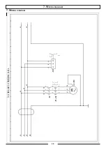
Page 20: ...7 Wiring diagram 20 7 Wiring diagram ...
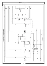
Page 21: ... 21 7 Wiring diagram ...
Page 22: ... 22 7 Wiring diagram ...
Page 23: ... 23 7 Wiring diagram ...
Page 24: ... 24 7 Wiring diagram ...
Page 25: ... 25 7 Wiring diagram ...
Page 26: ... 26 7 Wiring diagram ...
Page 27: ... 27 7 Wiring diagram ...
Page 28: ... 28 7 Wiring diagram ...
Page 29: ... 29 7 Wiring diagram ...
Page 30: ... 30 7 Wiring diagram ...
Page 31: ... 31 7 Wiring diagram ...
Page 32: ... 32 7 Wiring diagram ...
Page 33: ... 33 7 Wiring diagram ...
Page 34: ... 34 7 Wiring diagram ...
Page 35: ... 35 7 Wiring diagram ...
Page 36: ... 36 7 Wiring diagram ...
Page 37: ...37 7 Wiring diagram 7 Wiring diagram ...
Page 38: ...38 7 Wiring diagram ...
Page 39: ...39 7 Wiring diagram ...
Page 40: ...40 7 Wiring diagram ...
Page 41: ...41 7 Wiring diagram ...
Page 42: ...42 7 Wiring diagram ...
Page 43: ...43 7 Wiring diagram ...
Page 44: ...44 7 Wiring diagram ...
Page 45: ...45 7 Wiring diagram ...
Page 46: ...46 7 Wiring diagram ...
Page 47: ...47 7 Wiring diagram ...
Page 48: ...48 7 Wiring diagram ...
Page 49: ...49 7 Wiring diagram ...
Page 50: ...50 7 Wiring diagram ...
Page 51: ...51 7 Wiring diagram ...
Page 52: ...52 7 Wiring diagram ...
Page 53: ...53 7 Wiring diagram ...
Page 54: ...54 7 Wiring diagram ...
Page 55: ...55 7 Wiring diagram ...
Page 56: ...56 7 Wiring diagram ...
Page 59: ...59 9 Maintence Schedule ...
Page 60: ...Cod 1127340124_02 2017 ...


